6.1.4.4 SIE & Buffer Control Registers
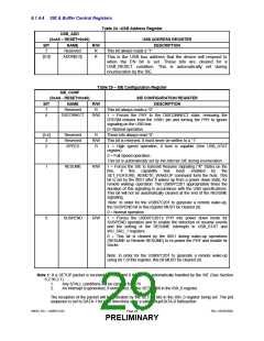
Table 24 –USB Address Register
USB_ADD
(0xA9 – RESET=0x00)
NAME
USB ADDRESS REGISTER
DESCRIPTION
BIT
R/W
R
7
Reserved
This bit always reads a “1”.
[6:0]
ADDR[6:0]
R
This is the USB bus address that the device will respond to
when the EN bit is set. These bits are cleared for a
USB_RESET condition. This is automatically set during
enumeration by the SIE.
Table 25 – SIE Configuration Register
SIE_CONF
(0xAA - RESET=0x40)
SIE CONFIGURATION REGISTER
DESCRIPTION
BIT
7
NAME
R/W
R
Reserved
This bit always reads a “0”.
DISCONNECT
6
R/W
1 = Forces the PHY to the DISCONNECT state, removing the
RTERM resistor from the USB+ pin and forcing the PHY to ignore
signaling on the USB bus.
0= Normal operation.
[5:4]
3
Reserved
Reserved
SPEED
R
R/W
R
These bits always read “0”.
This bit is reserved. It must never be written to a “1”.
2
1 = High speed operation, if host is capable (See USB_STAT
register).
0 = Full Speed operation.
This bit is automatically set by the internal SIE during enumeration.
1
RESUME
R/W
1 = Forces the SIE to transmit Resume Signaling (“K” State) on the
line,
if
this
capability
has
been
enabled
by
the
SET_FEATURE_REMOTE_WAKEUP command form the host. This
bit is set by the 8051 after it wakes up from a power down state, for
remote wakeup operation. The USB97C201 appropriately times the
duration of this signaling in accordance with the USB specifications.
This bit will not be automatically cleared at the end of the RESUME
signaling.
Note: In order for the USB97C201 to generate a remote wake-up,
the SUSPEND bit in this register MUST be cleared (0).
0 = Normal operation
0
SUSPEND
R/W
1 = Forces the USB97C201’s PHY into power down mode for
SUSPEND operation and to enable the detection of resume events
and the setting of the RESUME interrupts in USB_STAT and
WU_SRC_1 registers.
0 = This bit is cleared by the 8051 during wake-up operations
(RESUME or Remote RESUME) to re-power the PHY and enable its
clocks.
Note: In order for the USB97C201 to generate a remote wake-up
using bit 1 of this register, this bit MUST be cleared (0).
Note 1: If a SETUP packet is received on Endpoint 0 that is not automatically handled by the SIE (See Section
6.2.36.2.1) :
1.
2.
Any STALL conditions will be cleared for EP0.
An interrupt is generated, if unmasked, by the SETUP bit in the ISR_0 register.
The reception of the packet will be indicated by the SETUP bits in the ISR_0 register being set. The pid
sequence is set to DATA-1 for both directions after a valid setup/DATA-0 transaction.
SMSC DS – USB97C201
Page 29
Rev. 03/25/2002
PRELIMINARY

 SMSC [ SMSC CORPORATION ]