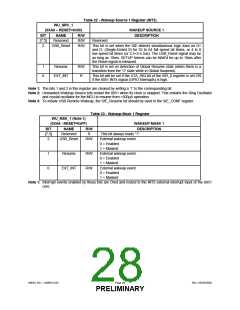
Table 22 - Wakeup Source 1 Register (INT2)
WAKEUP SOURCE 1
WU_SRC_1
(0XA0 – RESET=0x00)
BIT
NAME
R/W
DESCRIPTION
[7:3]
2
Reserved
USB_Reset
R/W
R/W
Reserved
This bit is set when the SIE detects simultaneous logic lows on D+
and D- (Single-Ended 0) for 32 to 64 full speed bit times, or 4 to 8
low speed bit times (or 2.5<t<5.5us). The USB_Reset signal may be
as long as 10ms. SETUP tokens can be NAK'd for up to 10ms after
the Reset signal is released.
1
0
Resume
EXT_INT
R/W
R
This bit is set on detection of Global Resume state (when there is a
transition from the "J" state while in Global Suspend).
This bit will be set if the ATA_IRQ bit of the ISR_0 register is set OR
if the 8051 INT4 signal (GPIO Interrupts) is high.
Note 1: The bits 1 and 2 in this register are cleared by writing a ‘1’ to the corresponding bit.
Note 2: Unmasked Wakeup Source bits restart the 8051 when its clock is stopped. This restarts the Ring Oscillator
and crystal oscillator for the MCU to resume from <500µA operation.
Note 3: To initiate USB Remote Wakeup, the SIE_Resume bit should be used in the SIE_CONF register.
Table 23 - Wakeup Mask 1 Register
WU_MSK_1 (Note 1)
(0XA6 - RESET=0xFF)
WAKEUP MASK 1
DESCRIPTION
BIT
NAME
R/W
[7:3]
2
Reserved
USB_Reset
R
This bit always reads “1”.
R/W
External wakeup event.
0 = Enabled
1 = Masked
1
0
Resume
EXT_INT
R/W
R/W
External wakeup event.
0 = Enabled
1 = Masked
External wakeup event.
0 = Enabled
1 = Masked
Note 1: Interrupt events enabled by these bits are Ored and routed to the INT2 external interrupt input of the 8051
core.
SMSC DS – USB97C201
Page 28
Rev. 03/25/2002
PRELIMINARY

 SMSC [ SMSC CORPORATION ]