Advanced I/O Controller with Motherboard GLUE Logic
Datasheet
Note:
The generation of a PME for this event is controlled by the PME enable bit (located in the PME_EN1
register at bit 5) when the logic for feature is turned on.
7.29 Fan Monitoring
The chip monitors the speed of the fans by utilizing fan tachometer input signals from fans equipped with
tachometer outputs. The fan tachometer inputs are monitored by using the Fan Tachometer registers.
These signals, as well as the Fan Tachometer registers, are described below.
7.29.1 Fan Tachometer Inputs
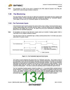
A fan tachometer input is used to measure the speed at which a fan is rotating. The fan tachometer input is
a train of square pulses with a 50% duty cycle (see Figure 7.5) that are derived from the magnetic fields
generated by the rotating rotor of the fan. The speed of the fan can be determined by calculating the
period of the Fan Tachometer input pulse.
Note:
All calculations are based on fans that emit 2 square pulses per revolution. Reading registers reflect a
count value for one complete revolution (2 pulses).
The clock source to the Fan Tachometer logic is 90kHz (nominal) derived from 14.318 MHz clock and is
active when VCC power is active.
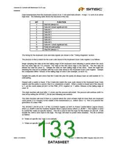
TR
Fan Tachometer Input
TR = Revolution Time = 60/RPM (sec)
TP
TP = Pulse Time = TR/2
(Two Pulses Per Revolution)
Clock Source for Counter
F = 90kHz (nominal)
Figure 7.5 – Fan Tachometer Input and Clock Source
The counter is used to determine the period of the Fan Tachometer input pulse. This counter is reset on
the rising edge of every other fan tachometer input pulse, and thus measures the number of clock pulses
generated by the clock source for the duration of one fan tachometer revolution. Since two fan tachometer
input pulses are generated per revolution of the fan rotor, the speed of the fan is easily calculated. The fan
tachometer input resets the counter on every other pulse and simultaneously loads the count into its
respective reading register. This value is used by the operating system to monitor the speed of the fan.
The Fan Tachometer Reading registers contain the number of 11.11us periods (90kHz nominal) between
full fan revolutions. Fans produce 2 pulses per revolution. These registers are updated at least once every
second. This register is latched on the rising edge of every other fan tachometer pulse and when the fan
count reaches FFFFh. The value FFFFh indicates that the fan is not spinning (stalled fan event), or the
tachometer input is not connected to a valid signal (this could be triggered by a counter overflow)
Revision 1.8 SMSC/Non-SMSC Register Sets (02-24-05)
134
SMSC LPC47M182
DATASHEET

 SMSC [ SMSC CORPORATION ]