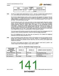
Advanced I/O Controller with Motherboard GLUE Logic
Datasheet
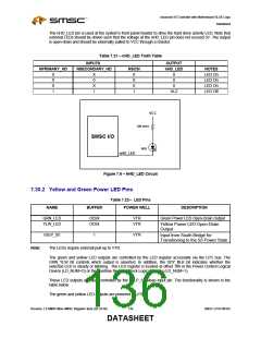
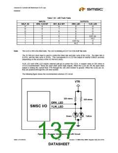
Table 7.23 - LED Truth Table
INPUTS
GRN_YLW BIT
OUTPUTS
NSLP_S5
SDY_BLK BIT
GRN_LED
YLW_LED
0
0
0
0
1
1
1
1
0
0
1
1
0
0
1
1
0
1
0
1
0
1
0
1
0
0
0
0
0
0
0
0
0
0.67 Hz
Hi-Z
0
0
0.67 Hz
Hi-Z
0
Note:
The LED is ON in the Hi-Z state. The LED is blinking at 0.67 Hz in the 0.67 Hz state.
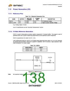
The 32.768 kHz clock input is used to control the blink rate and duty cycle of the LEDs. The blink rate is
0.67Hz, and the duty cycle is 39.6%. This corresponds to a LED low output of exactly 0.90625 seconds
(depending on the accuracy of the 32.768 kHz clock).
YLW_LED and GRN_LED require external pull-ups to power the LEDs. A resistor value of 220 ohms to
VTR is recommended. These are open drain active high outputs. When the LEDs are off, the open drain
output is sinking the current from VTR through the 220 ohm resistor to ground. When the LEDs are on,
they are powered through the 220 ohm resistor.
The following figure shows the recommended external LED circuit.
VTR
220 ohms
220 ohms
GRN_LED
YLW_LED
SMSC I/O
Green
Yellow
Figure 7.7 – Example Yellow and Green LED Circuit
SMSC LPC47M182
137
Revision 1.8 SMSC/Non-SMSC Register Sets (02-24-05)
DATASHEET

 SMSC [ SMSC CORPORATION ]