Advanced I/O Controller with Motherboard GLUE Logic
Datasheet
0x16in the Power Control Logical Device, when LD_NUM=0, or Runtime Register Block Logical Device,
when LD_NUM=1. See the “Power Control Runtime Registers” and “Runtime Register Block Runtime
Registers” sections.
The PME functionality is controlled by the PME status and enable registers defined in the “Power Control
Runtime Registers” and “Runtime Register Block Runtime Registers” section, is located at the address
programmed in configuration registers 0x60 and 0x61 in Power Control/Runtime Register Logical Device.
The Power Control Logical Device is selected when LD_NUM=0, and the runtime Registers Locial Device
is selected when LD_NUM=1. The PME Enable bit, PME_EN, globally controls PME Wake-up events.
When PME_EN is inactive, the nIO_PME signal can not be asserted. When PME_EN is asserted, any
wake source whose individual PME Wake Enable register bit is asserted can cause nIO_PME to become
asserted.
The PME Status register indicates that an enabled wake source has occurred, and if the PME_EN bit is
set, asserted the nIO_PME signal. The PME Status bit is asserted by active transitions of PME wake
sources. PME_Status will become asserted independent of the state of the global PME enable bit,
PME_EN.
The following pertains to the PME status bits for each event:
The output of the status bit for each event is combined with the corresponding enable bit to set the PME
status bit.
The status bit for any pending events must be cleared in order to clear the PME_STS bit. Status bits are
cleared on a write of ‘1’.
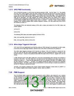
For the GPIO events, the polarity of the edge used to set the status bit and generate a PME is controlled
by the polarity bit of the GPIO control register. For non-inverted polarity (default) the status bit is set on
the low-to-high edge. If the EETI function is selected for a GPIO then both a high-to-low and a low-to-high
edge will set the corresponding PME status bits. Status bits are cleared on a write of ‘1’.
The PME Wake registers also include status and enable bits for the fan tachometer input. The fan
tachometers are not intended to be wakeup events and are only valid when VCC power is active. User
Note: Clear the PME enable bits for the fan tachometers before removing VCC.
See the “Keyboard and Mouse PME Generation” section for information about using the keyboard and
mouse signals to generate a PME.
In the LPC47M182 the nIO_PME pin can be programmed to be an open drain, active low, driver. The
LPC47M182 nIO_PME pin is fully isolated from other external devices that might pull the nIO_PME signal
low; i.e., the nIO_PME signal is capable of being driven high externally by another active device or pullup
even when the LPC47M182 VCC is grounded, providing VTR power is active. The LPC47M182 nIO_PME
driver sinks 6mA at .55V max (see section 4.2.1.1 DC Specifications, page 122, in the “PCI Local Bus
Specification,” revision 2.1).
7.28.1 ‘Wake on Specific Key’ Option
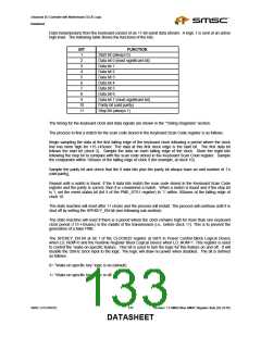
The LPC47M182 has logic to detect a single keyboard scan code for wakeup (PME generation). The scan
code is programmed onto the Keyboard Scan Code Register, a runtime register at offset 0x11 from the
base address located in the primary base I/O address in Power Control Block Logical Device when
LD_NUM =0, or the Runtime Register Block Logical Device when LD_NUM =1. This register is powered
by VTR and reset on VTR POR.
The PME status bit for this event is located in the PME_STS1 register at bit 5 and the PME enable bit for
this event is located in the PME_EN1 register at bit 5. See the “Power Control Runtime Registers”
sections for a definition of these registers.
Revision 1.8 SMSC/Non-SMSC Register Sets (02-24-05)
132
SMSC LPC47M182
DATASHEET

 SMSC [ SMSC CORPORATION ]