Advanced I/O Controller with Motherboard GLUE Logic
Datasheet
The Fan Tachometer Reading registers always return an accurate fan tachometer measurement, even
when a fan is disabled or non-functional.
The Tachometer Reading registers are 16 bits, unsigned. When one byte of a 16-bit register is read, the
other byte latches the current value until it is read, in order to ensure a valid reading. The order is LSB
first, MSB second. These registers are read only – a write to these registers has no effect.
The fan tachometer reading registers are Tach1 LSB, Tach1_MSB, Tach2 LSB and Tach2 MSB. See
“Power Control Runtime Registers” section when LD_NUM=0 and “Runtime Register Block Runtime
Registers” section when LD_NUM=1.
7.29.2 Detection of a Stalled Fan
The fan failure bit in the interrupt status register is set in the event of a stalled fan. Note: the fan
tachometer reading register, which holds the count value, does not roll over – it stays at FFFFh in the
event of a stalled fan. The internal count register does rollover, however, and continuously counts to
FFFFh as long as the fan is stalled.
In the event the counter reaches FFFFh, the PME status bit is set and the count value is latched into the
register. The second subsequent fan tach pulse resets the counter but does not latch the count value.
Every second fan tach pulse latches the fan count value into the fan tachometer register except for this
special case.
The fan stalled event can generate a PME if properly enabled. Note the fan stalled PME is not a wakeup
event, and it can indicate a fan stalled event if VCC is active.
7.30 Hard Drive and Power LED Logic
7.30.1 Hard Drive Front Panel LED (Red)
Table 7.20 – Hard Drive Front Panel Pins
POWER
NAME
BUFFER
DESCRIPTION
WELL
VCC
nSCSI
ISPU_400
OD12
SCSI Drive Active Input
nHD_LED
VCC
Hard Drive Front Panel LED
Open-Drain Output
nSECONDARY_HD
nPRIMARY_HD
ISPU_400
ISPU_400
VCC
VCC
IDE Secondary Drive Active
Input
IDE Primary Drive Active Input
Notes:
The nHD_LED requires external pull-up to VCC.
ISPU_400 is defined as: Input with Schmitt Trigger, 400 mV hysteresis, with 30uA internal pull-up.
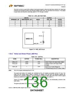
The nHD_LED pin is a logical AND of the inputs nPRIMARY_HD, nSECONDARY_HD and nSCSI
used to drive a single color LED. The inputs are internally pulled to VCC. See table below for state
definitions.
SMSC LPC47M182
135
Revision 1.8 SMSC/Non-SMSC Register Sets (02-24-05)
DATASHEET

 SMSC [ SMSC CORPORATION ]