Advanced I/O Controller with Motherboard GLUE Logic
Datasheet
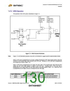
7.27.5 GPIO PME Functionality
The LPC47M182 provides 12 GPIOs that can directly generate a PME. See the Table 7.16. The polarity
bit in the GPIO control registers select the edge on these GPIO pins that will set the associated status bit
in the PME_STS2 and PME_STS3 registers. The default is the low-to-high edge. If the corresponding
enable bit in the PME_EN2 and PME_EN3 registers and the PME_EN bit in the PME_EN register is set, a
PME will be generated. The PME registers are runtime registers which are located at the address
contained in the configuration registers 0x60 and 0x61 in Power Control Logical Device when LD_NUM=0
or the Runtime Register Block Logical Device when LD_NUM=1. See the “Power Control Runtime
Registers” and “Runtime Register Block Runtime Registers” sections. The PME status bits for the GPIOs
are cleared on a write of ‘1’.
The following GPIOs are dedicated wakeup GPIOs with a status and enable bit in the PME status and
enable registers:
GP10-GP17
GP20-GP23
The following PME status and enable registers for these GPIOs:
PME_STS2 and PME_EN2 for GP10-GP17
PME_STS3 and PME_EN3 for GP20-GP23
7.27.6 Either Edge Triggered Interrupts
GP21 and GP22 are implemented such that they allow an PME interrupt to be generated on both a high-
to-low and a low-to-high edge transition, instead of one or the other as selected by the polarity bit.
The either edge triggered interrupts (EETI) function as follows: If the EETI function is selected for the
GPIO pin, then the bits that control input/output, polarity and open drain/push-pull have no effect on the
function of the pin. However, the polarity bit does affect the value of the GP bit (i.e., register GP2, bit 2 for
GP22).
A PME interrupt occurs if the PME enable bit is set for the corresponding GPIO and the EETI function is
selected on the GPIO. The PME status bit is set when the EETI pin transitions (on either edge) and are
cleared on a write of ‘1’. There are also status bits for the EETIs located in the MSC_STS register, which
are also cleared on a write of ‘1’. The MSC_STS register provides the status of all of the EETI interrupts
within one register. The PME or MSC status is valid whether or not the interrupt is enabled and whether or
not the EETI function is selected for the pin.
The MSC_STS register is defined in the “Power Control Runtime Registers” section when LD_NUM=0 or
the “Runtime Register Block Runtime Registers” section when LD_NUM=1.
7.28 PME Support
The LPC47M182 offers support for power management events (PMEs), also referred to as a System
Control Interrupt (SCI) events in an ACPI system. A power management event is indicated to the chipset
via the assertion of the nIO_PME signal. In the LPC47M182, the nIO_PME is asserted by active
transitions on the ring indicator inputs nRI1 and nRI2, active keyboard-data edges, active mouse-data
edges, programmable edges on GPIO pins and fan tachometer event. The nIO_PME pin, can be
programmed to be active high or active low via the polarity bit in the nIO_PME Register. The output buffer
type of the pin can be programmed to be open-drain or push-pull via bit 7 of the nIO_PME Register. The
nIO_PME pin function defaults to active low, open-drain output. The nIO_PME Register is located at offset
SMSC LPC47M182
131
Revision 1.8 SMSC/Non-SMSC Register Sets (02-24-05)
DATASHEET

 SMSC [ SMSC CORPORATION ]