Advanced I/O Controller with Motherboard GLUE Logic
Datasheet
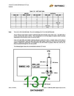
The nHD_LED pin is used at the system’s front panel header to drive the hard drive activity LED. Note that
external LEDs should be driven such that the voltage at the nHD_LED pin does not exceed 5V. The output
is open-drain and should be externally pulled to VCC through a resistor.
Table 7.21 – nHD_LED Truth Table
INPUTS
NSECONDARY_HD
OUTPUT
nHD_LED
NPRIMARY_HD
NSCSI
NOTES
LED On
LED On
LED On
LED Off
0
X
X
1
X
0
X
1
X
X
0
0
0
0
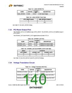
1
Hi-Z
VCC
220 ohms
SMSC I/O
RED
nHD_LED
Figure 7.6 – NHD_LED Circuit
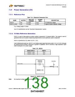
7.30.2 Yellow and Green Power LED Pins
Table 7.22-- LED Pins
NAME
BUFFER
POWER WELL
DESCRIPTION
GRN_LED
YLW_LED
OD24
OD24
VTR
VTR
Green Power LED Open-Drain Output
Yellow Power LED Open-Drain
Output
nSLP_S5
I
VTR
Input from South Bridge for
Transitioning to the S5 Power State
Note:
The LEDs require external pull-up to VTR.
The green and yellow LED outputs are controlled by the LED register accessible via the LPC bus. The
GRN_YLW bit controls which output is asserted. In addition, the SDY_BLK bit indicates whether the
selected LED is steady or blinking. The LED register is located at offset 10h in the Power Control Logical
Device (LD_NUM=O) or the Runtime Register Block Logical Device (LD_NUM=1).
These LED outputs are also controlled by the nSLP_S5 sleep input pin. The functionality is shown in the
table below.
The green and yellow LED outputs are powered by VTR.
Revision 1.8 SMSC/Non-SMSC Register Sets (02-24-05)
136
SMSC LPC47M182
DATASHEET

 SMSC [ SMSC CORPORATION ]