setting of the time. When the divider chain is changed from reset to the operating mode, the first update cycle is
one-half second later.
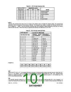
Periodic Interrupt Selection
The periodic interrupt allows the IRQB port to be triggered from once every 500 ms to once every 122.07 μs. As
Table 51 shows, the periodic interrupt is selected with the RS0-RS3 bits in Register A. The periodic interrupt is
enabled with the PIE bit in Register B.
6.9.8 32KHZ CLOCK INPUT
The XOSEL pin is used to select either a 32.768kHz input clock or a 32.768kHz crystal to drive the Real Time Clock
Interface).
When XOSEL = ‘0’, the RTC uses a 32.768kHz crystal connected between the XTAL1 and XTAL2 pins. When
XOSEL = ‘1’, the RTC is driven by a 32.768kHz single-ended clock source connected to the XTAL2 pin.
Note: Standby current on Vbat is <1µA.
6.9.9 POWER MANAGEMENT
The RTC and CMOS RAM utilize VBAT power plane.
The VTR POR does not affect the clock, calendar, or RAM functions. When VTR POR is active, the following occurs:
Periodic Interrupt Enable (PIE) is cleared to “0”.
Alarm Interrupt Enable (AIE) bit is cleared to “0”.
Update Ended Interrupt Enable (UIE) bit is cleared to “0”.
Update Ended Interrupt Flag (UF) bit is cleared to “0”.
Interrupt Request status Flag (IRQF) bit is cleared to “0”.
Periodic Interrupt Flag (PIF) is cleared to “0”.
The RTC and CMOS registers are not accessible.
Alarm Interrupt Flag (AF) is cleared to “0”.
RTC IRQ is not enabled
If both the main power (VTR) and the battery power (VBAT) are both low at the same time and then re-applied (i.e. a
new battery is installed) the following occurs:
Initialize all registers 00-0D to a “00” when VTR is applied.
The oscillator is disabled immediately.
The VRT bit is cleared to “0”.
When PWRGD = 0, all host inputs are locked out so that the internal registers cannot be modified by the host system.
The Host lockout condition continues for 500usec (min) to 1msec (max) after PWRGD =1. The Host lockout condition
does not occur when either of the following occurs:
-
-
RTC Divider Selection mode is not in normal mode in Table 50.
The VRT bit in Register D is a "0".
SMSC DS – LPC47S45x
Page 104 of 259
Rev. 07/09/2001
DATASHEET

 SMSC [ SMSC CORPORATION ]