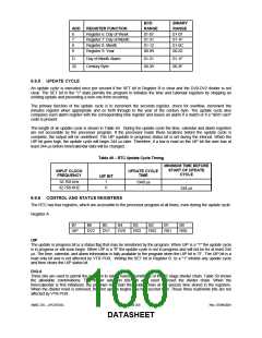
BCD
BINARY
RANGE
01-07
ADD
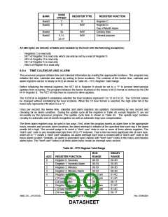
REGISTER FUNCTION
Register 6: Day of Week
Register 7: Day of Month
Register 8: Month
RANGE
01-07
01-31
01-12
00-99
6
7
8
9
01-1F
01-0C
00-63
Register 9: Year
D
Day of Month Alarm
Century Byte
01-31
00-39
01-1F
00-3F
32
6.9.5 UPDATE CYCLE
An update cycle is executed once per second if the SET bit in Register B is clear and the DV0-DV2 divider is not
clear. The SET bit in the "1" state permits the program to initialize the time and calendar registers by stopping an
existing update and preventing a new one from occurring.
The primary function of the update cycle is to increment the seconds register, check for overflow, increment the
minutes register when appropriate and so forth through to the year of the century byte. The update cycle also
compares each alarm register with the corresponding time register and issues an alarm if a match or if a "don't care"
code is present.
The length of an update cycle is shown in Table 49. During the update cycle the time, calendar and alarm registers
are not accessible by the processor program. If the processor reads these locations before the update cycle is
complete, the output will be undefined. The UIP (update in progress) status bit is set during the interval. When the
UIP bit goes high, the update cycle will begin 244 μs later. Therefore, if a low is read on the UIP bit the user has at
least 244 μs before time/calendar data will be changed.
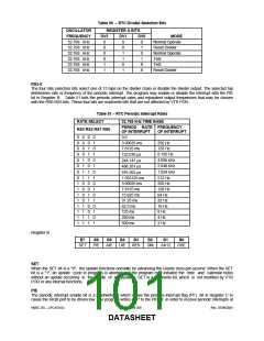
Table 49 − RTC Update Cycle Timing
MINIMUM TIME BEFORE
START OF UPDATE
CYCLE
INPUT CLOCK
FREQUENCY
UPDATE CYCLE
TIME
UIP BIT
32.768 kHz
32.768 KHZ
1
0
-
1948 μs
-
244 μs
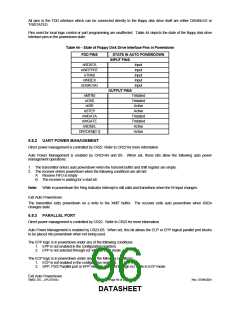
6.9.6 CONTROL AND STATUS REGISTERS
The RTC has four registers, which are accessible to the processor program at all times, even during the update cycle.
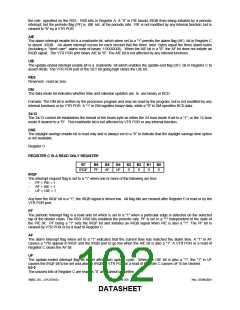
Register A
B7
B6
B5
B4
B3
B2
B1
B0
UIP
DV2
DV1
DV0
RS3
RS2
RS1
RS0
UIP
The update in progress bit is a status flag that may be monitored by the program. When UIP is a "1" the update cycle
is in progress or will soon begin. When UIP is a "0" the update cycle is not in progress and will not be for at least 244
μs. The time, calendar, and alarm information is fully available to the program when the UIP bit is “0”. The UIP bit is a
read only bit and is not affected by VTR POR. Writing the SET bit in Register B to a "1" inhibits any update cycle
and then clears the UIP status bit.
DV2-0
Three bits are used to permit the program to select various conditions of the 22 stage divider chain. Table 50 shows
the allowable combinations. The divider selection bits are also used to reset the divider chain. When the
time/calendar is first initialized, the program may start the divider chain at the precise time stored in the registers.
When the divider reset is removed, the first update begins one-half second later. These three read/write bits are not
affected by VTR POR.
SMSC DS – LPC47S45x
Page 100 of 259
Rev. 07/09/2001
DATASHEET

 SMSC [ SMSC CORPORATION ]