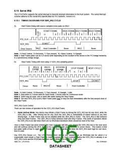
2. Continuous (Idle) Mode: Only the Host controller can initiate a Start Frame to update IRQ/Data line information.
All other SER_IRQ agents become passive and may not initiate a Start Frame. SER_IRQ will be driven low for
four to eight clocks by Host Controller. This mode has two functions. It can be used to stop or idle the SER_IRQ
or the Host Controller can operate SER_IRQ in a continuous mode by initiating a Start Frame at the end of every
Stop Frame.
An SER_IRQ mode transition can only occur during the Stop Frame. Upon reset, SER_IRQ bus is defaulted to
Continuous mode, therefore only the Host controller can initiate the first Start Frame. Slaves must
continuously sample the Stop Frames pulse width to determine the next SER_IRQ Cycle’s mode.
SER_IRQ Data Frame
Once a Start Frame has been initiated, the LPC47S45x will watch for the rising edge of the Start Pulse and start
counting IRQ/Data Frames from there. Each IRQ/Data Frame is three clocks: Sample phase, Recovery phase, and
Turn-around phase. During the Sample phase the LPC47S45x drives the SER_IRQ low, if and only if, its last
detected IRQ/Data value was low. If its detected IRQ/Data value is high, SER_IRQ is left tri-stated. During the
Recovery phase the LPC47S45x drives the SER_IRQ high, if and only if, it had driven the SER_IRQ low during the
previous Sample Phase. During the Turn-around Phase the LPC47S45x tri-states the SER_IRQ. The LPC47S45x
will drive the SER_IRQ line low at the appropriate sample point if its associated IRQ/Data line is low, regardless of
which device initiated the Start Frame.
The Sample Phase for each IRQ/Data follows the low to high transition of the Start Frame pulse by a number of
clocks equal to the IRQ/Data Frame times three, minus one. (e.g. The IRQ5 Sample clock is the sixth IRQ/Data
Frame, (6 x 3) - 1 = 17th clock after the rising edge of the Start Pulse).
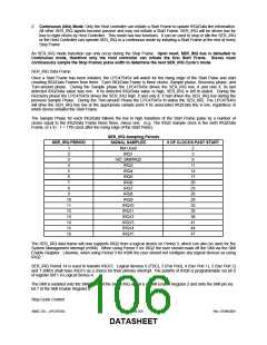
SER_IRQ Sampling Periods
SER_IRQ PERIOD
SIGNAL SAMPLED
Not Used
IRQ1
# OF CLOCKS PAST START
1
2
2
5
3
nIO_SMI/IRQ2
IRQ3
8
4
11
14
17
20
23
26
29
32
35
38
41
44
47
5
IRQ4
6
IRQ5
7
IRQ6
8
IRQ7
9
IRQ8
10
11
12
13
14
15
16
IRQ9
IRQ10
IRQ11
IRQ12
IRQ13
IRQ14
IRQ15
The SER_IRQ data frame will now supports IRQ2 from a logical device on Period 3, which can also be used for the
System Management Interrupt (nSMI). When using Period 3 for IRQ2 the user should mask off the SMI via the SMI
Enable Register. Likewise, when using Period 3 for nSMI the user should not configure any logical devices as using
IRQ2.
SER_IRQ Period 14 is used to transfer IRQ13. Logical devices 0 (FDC), 3 (Par Port), 4 (Ser Port 1), 5 (Ser Port 2)
and 7 (KBD) shall have IRQ13 as a choice for their primary interrupt. The polarity of IRQ8 is programmable via bit 0
of register 0xF1 in Logical Device A.
The SMI is enabled onto the SMI frame of the Serial IRQ via bit 6 of SMI Enable Register 2 and onto the SMI pin via
bit 7 of the SMI Enable Register 2.
Stop Cycle Control
SMSC DS – LPC47S45x
Page 106 of 259
Rev. 07/09/2001
DATASHEET

 SMSC [ SMSC CORPORATION ]