the rate specified by the RS3 - RS0 bits in Register A. A “0” in PIE blocks IRQB from being initiated by a periodic
interrupt, but the periodic flag (PF) is still set at the periodic rate. PIE is not modified by any internal function, but is
cleared to "0" by a VTR POR.
AIE
The alarm interrupt enable bit is a read/write bit, which when set to a "1" permits the alarm flag (AF) bit in Register C
to assert IRQB. An alarm interrupt occurs for each second that the three time bytes equal the three alarm bytes
(including a "don't care" alarm code of binary 11XXXXXX). When the AIE bit is a "0", the AF bit does not initiate an
IRQB signal. The VTR POR port clears AIE to "0". The AIE bit is not affected by any internal functions.
UIE
The update-ended interrupt enable bit is a read/write bit which enables the update-end flag (UF) bit in Register C to
assert IRQB. The VTR POR port or the SET bit going high clears the UIE bit.
RES
Reserved - read as zero
DM
The data mode bit indicates whether time and calendar updates are to use binary or BCD
Formats: The DM bit is written by the processor program and may be read by the program, but is not modified by any
internal functions or by VTR POR. A "1” in DM signifies binary data, while a "0" in DM specifies BCD data.
24/12
The 24/12 control bit establishes the format of the hours byte as either the 24 hour mode if set to a "1", or the 12 hour
mode if cleared to a "0". This read/write bit is not affected by VTR POR or any internal function.
DSE
The daylight savings enable bit is read only and is always set to a "0” to indicate that the daylight savings time option
is not available.
Register C
REGISTER C IS A READ ONLY REGISTER
B7
B6
B5
B4
B3
B2
B1
B0
IRQF
PF
AF
UF
0
0
0
0
IRQF
The interrupt request flag is set to a "1” when one or more of the following are true:
-
-
-
PF = PIE = 1
AF = AIE = 1
UF = UIE = 1
Any time the IRQF bit is a "1", the IRQB signal is driven low. All flag bits are cleared after Register C is read or by the
VTR POR port.
PF
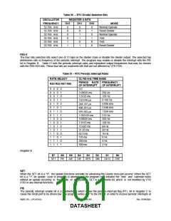
The periodic interrupt flag is a read only bit which is set to a "1" when a particular edge is detected on the selected
tap of the divider chain. The RS3 -RS0 bits establish the periodic rate. PF is set to a "1" independent of the state of
the PIE bit. PF being a "1" sets the IRQF bit and initiates an IRQB signal when PIE is also a "1". The PF bit is
cleared by VTR POR or by a read of Register C.
AF
The alarm interrupt flag when set to a "1" indicates that the current time has matched the alarm time. A "1" in AF
causes a "1"to appear in IRQF and the IRQB port to go low when the AIE bit is also a "1". A VTR POR or a read of
Register C clears the AF bit.
UF
The update-ended interrupt flag bit is set after each update cycle. When the UIE bit is also a "1", the "1" in UF
causes the IRQF bit to be set and asserts IRQB. A VTR POR or a read of Register C causes UF to be cleared.
b3-0
The unused bits of Register C are read as “0” and cannot be written.
SMSC DS – LPC47S45x
Page 102 of 259
Rev. 07/09/2001
DATASHEET

 SMSC [ SMSC CORPORATION ]