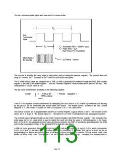
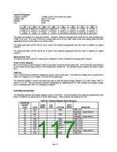
The fan tachometer input signal and clock source is shown below.
TR
Fan
Tachometer
Input
TP
TR = Revolution Time = 60/RPM (sec)
TP = Pulse Time = TR/2
(Two Pulses Per Revolution)
Clock Source
for Counter
F = 32.786kHz ÷ Divisor
The counter is reset by the rising edge of each pulse (and by writing the preload register). The counter does not
wrap; if it reaches 0xFF, it remains at 0xFF until it is reset by the next pulse.
The 2 MSBs of the count are sampled and a PME or SMI is generated (if enabled through the PME_EN1 enable
register or the SMI_EN5 enable register - see the “Runtime Registers” section) when these two bits are set. This
corresponds to a count value of 192.
The fan count is determined according to the following equation:
Count =
1
2
x
1.966 x 106
RPM x Divisor
+ Preload (Equation 1)
(Term 1)
Term 1 in the equation above is determined by multiplying the clock source of 32.768kHz by 60sec/min and dividing
by the product of the revolutions per minute times the divisor. The default divisor, located in the Fan Control
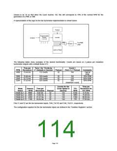
Register, is 2. This results in a value for Term 1 in Equation 1 of 111 for a 4400 RPM.
The divisor for each fan is programmable via the Fan Control Register, Logical Device 8, 0xFA. The choices for the
divisor are 1, 2, 4 and 8. The default value is 2. The factor of ½ in Term 1 corresponds to two pulses per revolution.
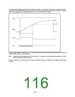
The preload value is programmable via the FAN1 Preload Register and FAN2 Preload Register. The preload is the
initial value for the fan count which is used to adjust the count such that the value of 192 corresponds to the “lower
limit” of the RPM. By setting the preload value and divisor properly, the PME or SMI will be generated when the RPM
reaches the desired percentage of the nominal RPM to indicate a fan failure.
A PME or SMI is generated, if enabled through the PME or SMI enable register, at a count of 192, which corresponds
to the “upper limit” for the fan count. This value is made to correspond to the “lower limit” of the RPM for the fan by
programming the divisor and preload value accordingly. Typical practice is to consider 70% of normal RPM a fan
failure, at which point Term 1 in Equation 1 for the example above will be 160. Therefore, the preload value is
Page 113

 SMSC [ SMSC CORPORATION ]