PME SUPPORT
The LPC47M10x offers support for power management events (PMEs). A power management event is requested by
a function via the assertion of the nIO_PME signal. In the LPC47M10x, the nIO_PME is asserted by active
transitions on the ring indicator inputs nRI1 and nRI2, valid NEC infrared remote control frames, active keyboard-data
edges, active mouse-data edges, programmable edges on GPIO pins and fan tachometer event. The
GP42/nIO_PME pin, when selected for the nIO_PME function, can be programmed to be active high or active low via
the polarity bit in the GP42 register. The output buffer type of the pin can be programmed to be open-drain or push-
pull via bit 7 of the GP42 register. The nIO_PME pin function defaults to active low, open-drain output.
The PME functionality is controlled by the PME status and enable registers in the runtime registers block, which is
located at the address programmed in configuration registers 0x60 and 0x61 in Logical Device A. The PME Enable
bit, PME_EN, globally controls PME Wake-up events. When PME_EN is inactive, the nIO_PME signal can not be
asserted. When PME_EN is asserted, any wake source whose individual PME Wake Enable register bit, is asserted
can cause nIO_PME to become asserted.
The PME_STS bit in the PME Wake Status register indicates that an enabled wake source has occurred, and if the
PME_EN bit is set, has asserted the nIO_PME signal. The PME Status bit is asserted by active transitions of enabled
PME Wake sources. PME_Status will become asserted independent of the state of the global PME enable bit,
PME_En.
The following pertains to the PME status bits for each event:
•
The output of the status bit for each event is combined with the corresponding enable bit to set the PME status
bit.
•
The status bit for any pending events must be cleared in order to clear the PME_STS bit.
For the GPIO events, the polarity of the edge used to set the status bit and generate a PME is controlled by the
polarity bit of the GPIO control register. For non-inverted polarity (default) the status bit is set on the low-to-high
edge. If the EETI function is selected for a GPIO then both a high-to-low and a low-to-high edge will set the
corresponding PME status bits. Status bits are cleared on a write of ‘1’.
The P12 function also has a polarity select bit in Configuration Register 0xF0 in Logical Device 1.
The PME Wake registers also include status and enable bits for the fan tachometer input.
See the “Keyboard and Mouse PME Generation” section for information about using the keyboard and mouse signals
to generate a PME.
In the LPC47M10x the nIO_PME pin can be programmed to be an open drain, active low, driver. The LPC47M10x
nIO_PME pin is fully isolated from other external devices that might pull the nIO_PME signal low; i.e., the nIO_PME
signal is capable of being driven high externally by another active device or pullup even when the LPC47M10x VCC
is grounded, providing VTR power is active. The LPC47M10x nIO_PME driver sinks 6mA at .55V max (see section
4.2.1.1 DC Specifications, page 122, in the PCI Local Bus Specification, Revision 2.1).
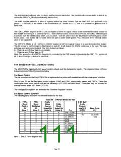
The PME registers are run-time registers as follows. These registers are located in system I/O space at an offset
from PME_BLK, the address programmed in Logical Device A at registers 0x60 and 0x61.
The following registers are for GPIO wakeup events:
PME Wake Status 2 (PME_STS2), PME Wake Enable 2 (PME_EN2)
PME Wake Status 3 (PME_STS3), PME Wake Enable 3 (PME_EN3)
PME Wake Status 4 (PME_STS4), PME Wake Enable 4 (PME_EN4)
PME Wake Status 5 (PME_STS5), PME Wake Enable 5 (PME_EN5)
See PME register description in the Runtime Register Section.
Enabling SMI Events onto the PME Pin
There is a bit in the PME Status Register 3 to show the status of the internal “group” SMI signal in the PME logic (if bit
5 of the SMI_EN2 register is set). This bit, DEVINT_STS, is at bit 3 of the PME_STS3 register. This bit is defined as
follows:
0=The group SMI output is inactive.
Page 109

 SMSC [ SMSC CORPORATION ]