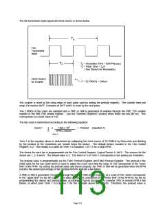
chosen to be 32 so that when the count reaches 192, this will correspond to 70% of the normal RPM for the
generation of a PME or SMI.
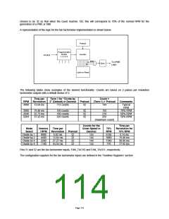
A representation of the logic for the fan tachometer implementation is shown below.
Preload
Programmable
Divider
1, 2, 4, 8
Counter
32 kHz
MSB
To nPME
Logic
Sync
Latch on Read
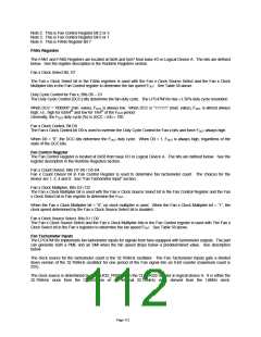
The following tables show examples of the desired functionality. Counts are based on 2 pulses per revolution
tachometer outputs with a default divisor of 2.
Time per
Revolution
13.64 ms
Term 1 for “Divide by
2” (Default) in Decimal
112 counts
Count =
(Term 1) + Preload
144
RPM
4400
Preload
Comments
Typical
32
RPM
3080
2640
2204
19.48 ms
22.73 ms
27.22 ms
160 counts
186 counts
223 counts
32
32
32
192
218
255
70% RPM
60% RPM
50% RPM
(maximum count)
Counts for the
Given Speed in
Time per
Revolution for
70% RPM
9.74 ms
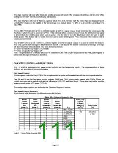
Mode
Select
Divide by 1
Divide by 2
Divide by 4
Divide by 8
Nomina
Time per
Revolution
6.82 ms
13.64 ms
27.27 ms
54.54 ms
70%
RPM
6160
3080
1540
770
l RPM
8800
4400
2200
1100
Preload
32
Decimal
144
144
144
32
32
32
19.48 ms
38.96 ms
77.92 ms
144
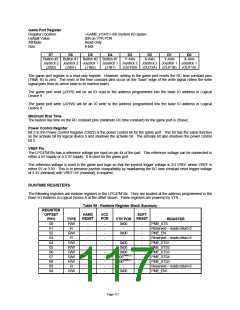
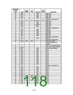
Pins 51 and 52 are the fan tachometer inputs, FAN_TACH2 and FAN_TACH1, respectively.
The configuration registers for the fan tachometer inputs are defined in the “Runtime Registers” section.
Page 114

 SMSC [ SMSC CORPORATION ]