CR21 - CR22
Registers CR21 - CR22 are Reserved. Reserved bits cannot be written and return 0 when read.
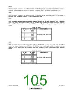
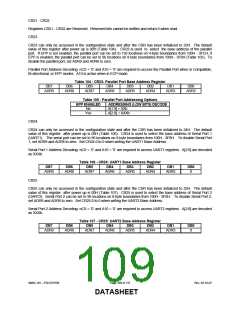
CR23
CR23 can only be accessed in the configuration state and after the CSR has been initialized to 23H. The default
value of this register after power up is 00H (Table 104). CR23 is used to select the base address of the parallel
port. If EPP is not enabled, the parallel port can be set to 192 locations on 4-byte boundaries from 100H - 3FCH; if
EPP is enabled, the parallel port can be set to 96 locations on 8-byte boundaries from 100H - 3F8H (Table 105). To
disable the parallel port, set ADR9 and ADR8 to zero.
Parallel Port Address Decoding: nCS = ’0’ and A10 = ’0’ are required to access the Parallel Port when in Compatible,
Bi-directional, or EPP modes. A10 is active when in ECP mode.
Table 104 - CR23: Parallel Port Base Address Register
DB7
DB6
DB5
DB4
DB3
DB2
DB1
DB0
ADR9
ADR8
ADR7
ADR6
ADR5
ADR4
ADR3
ADR2
Table 105 - Parallel Port Addressing Options
EPP ENABLED
ADDRESSING (LOW BITS) DECODE
A[1:0] = XXb
No
Yes
A[2:0] = XXXb
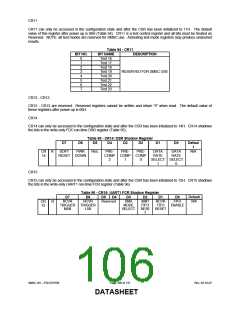
CR24
CR24 can only be accessed in the configuration state and after the CSR has been initialized to 24H. The default
value of this register after power up is 00H (Table 106). CR24 is used to select the base address of Serial Port 1
(UART1). The serial port can be set to 96 locations on 8-byte boundaries from 100H - 3F8H. To disable Serial Port
1, set ADR9 and ADR8 to zero. Set CR24.0 to 0 when writing the UART1 Base Address.
Serial Port 1 Address Decoding: nCS = ’0’ and A10 = ’0’ are required to access UART1 registers. A[2:0] are decoded
as XXXb.
Table 106 - CR24: UART1 Base Address Register
DB7
DB6
DB5
DB4
DB3
DB2
DB1
DB0
ADR9
ADR8
ADR7
ADR6
ADR5
ADR4
ADR3
0
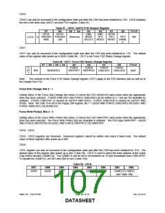
CR25
CR25 can only be accessed in the configuration state and after the CSR has been initialized to 25H. The default
value of this register after power up is 00H (Table 107). CR25 is used to select the base address of Serial Port 2
(UART2). Serial Port 2 can be set to 96 locations on 8-byte boundaries from 100H - 3F8H. To disable Serial Port 2,
set ADR9 and ADR8 to zero. Set CR25.0 to 0 when writing the UART2 Base Address.
Serial Port 2 Address Decoding: nCS = ’0’ and A10 = ’0’ are required to access UART2 registers. A[2:0] are decoded
as XXXb.
Table 107 - CR25: UART2 Base Address Register
DB7
DB6
DB5
DB4
DB3
DB2
DB1
DB0
ADR9
ADR8
ADR7
ADR6
ADR5
ADR4
ADR3
0
SMSC DS – FDC37N769
Page 109 of 137
Rev. 02-16-07
DATASHEET

 SMSC [ SMSC CORPORATION ]