Legacy-Free Keyboard/Embedded Controller with SPI and LPC Docking Interface
9.9.2
DMS Operation
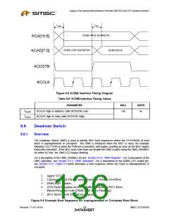
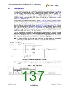
The DMS consists of a counter with a carry output, clock input, clear input and a count control input; a
32.768kHz RTC timebase input; an nDMS_LED output pin; and count/clear control logic (Figure 9.10).
The DMS counter is an 11-bit binary counter. When the counter is cleared, using the 32.768kHz RTC
timebase, the DMS counter carry output will be asserted 62.5ms after counting begins. When the carry
output is asserted, the counter clock is stopped, the DMS_OVERFLOW bit is asserted and the DMS
LED begins flashing. For a description of the nDMS_LED output pin (not shown in Figure 9.10) see
Section 9.9.3, "nDMS_LED Pin".
There are four basic DMS operating states as shown in Table 9.9: Initialize, Counting, Overflow,
Disabled. The DMS can also be enabled for test purposes (see Section 9.9.4.2, "DMS_TEST Bit – D1").
In normal operation, the DMS Initialize state occurs as a result of VCC1 POR. The Initialize state can
also occur when the PGM pin is asserted (see Section 9.6, "ATE Flash Program Access") or when the
DMS_TEST bit is asserted (see Section 9.9.4, "DMS Register"). In normal operation, the DMS Counting
state begins when the 8051 begins executing program code. The DMS Counting state also occurs
during DMS testing. The DMS Counting state can be terminated by the DMS_DISABLE bit, the DMS
Counter carry output, 8051_RESET or the DMS_TEST bit.
The DMS Overflow state occurs when the DMS Counter carry output is asserted. The DMS Overflow
state occurs when the 8051 boot block is unprogrammed or corrupted, or during DMS testing. In normal
operation, the DMS Disable state occurs when the 8051 asserts the DMS_DISABLE bit. Typically, the
DMS Disable state persists until the next VCC1 POR or until DMS testing begins.
Note: In normal operation, the 8051 boot code must assert the DMS_DISABLE bit before within
62.5ms to prevent the DMS Overflow state from asserting the DMS LED indicator.
DMS_TEST
8051_RESET
CLEAR
11-BIT
32.768kHz
CLOCK
CARRY
DMS_LED_ACTIVE
COUNTER
COUNT
DMS_DISABLE
Figure 9.10 Deadman Switch Block Diagram
Note: This figure is for illustration purposes only and is not intended to suggest specific implementation
details.
Table 9.9 DMS Truth Table
DMS CONTROLS
8051_RESET
OR
ITEM #
DMS_TEST
DMS_DISABLE CARRY
DMS STATE
DESCRIPTION
SMSC LPC47N350
119
Revision 1.1 (01-14-03)
DATASHEET

 SMSC [ SMSC CORPORATION ]