Legacy-Free Keyboard/Embedded Controller with SPI and LPC Docking Interface
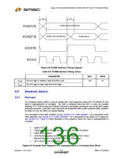
TADDR
TDATA
ROM HIGH ADDRESS
KCA[15:8]
KCAD[7:0]
ROM LOW ADDRESS
ROM DATA
KCDSTB
KCCLK
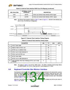
Figure 9.8 KCBM Interface Timing Diagram
Table 9.8 KCBM Interface Timing Values
PARAMETER
MAX
UNITS
T
KCCLK High to Address Valid (KCDSTB Low)
<30
ns
ADDR
T
KCCLK High to Data Valid (KCDSTB High)
DATA
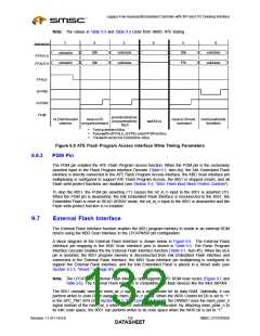
9.9
Deadman Switch
9.9.1
Overview
The Deadman Switch (DMS) is used to identify 8051 boot sequences where the LPC47N350 2k boot
block is unprogrammed or corrupted. The DMS is initialized when the 8051 is reset, for example
following VCC1 POR or when the PGM pin is asserted, and begins counting as soon as the 8051 begins
instruction execution. If the 8051 boot code does not disable the DMS counter using the DMS_DISABLE
bit within 62.5ms, the DMS LED begins flashing.
For a description of the DMS_DISABLE bit see, Section 9.9.4, "DMS Register". For a description of the
DMS Operation, see Section 9.9.2, "DMS Operation". For a description of the nDMS_LED output pin,
see Section 9.9.3. Figure 9.9 which illustrates a boot sequence where the Flash is unprogrammed or
corrupted.
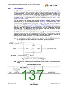
1. Apply VCC1
2. Unprogrammed Flash Causes Deadman Switch Overflow
3. DMS LED Flashes
4. ATE Flash Program Access Interface Initializes 8051 Boot
Block/Program Code (DMS LED Stops Flashing)
5. 8051 Boot Block Execution Begins
Figure 9.9 Example Boot Sequence for Unprogrammed or Corrupted Boot Block
Revision 1.1 (01-14-03)
118
SMSC LPC47N350
DATASHEET

 SMSC [ SMSC CORPORATION ]