Legacy-Free Keyboard/Embedded Controller with SPI and LPC Docking Interface
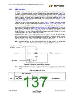
Table 9.9 DMS Truth Table (continued)
1
1
0
0
0
INITIALIZE
The 8051_RESET is asserted
because of VCC1 POR or the PGM
pin, or the DMS is in test mode. The
DMS counter is cleared, the DMS
LED is not flashing, and the DMS
counter is stopped.
2
3
COUNTING
OVERFLOW
DMS is counting. In normal
operation, the 8051 must set the
DMS_DISABLE bit before the DMS
counter overflows and activates the
DMS LED.
1
0
The 8051 has not disabled the DMS
in time to prevent the DMS LED from
flashing. The Flash is probably
unprogrammed or corrupted, or the
DMS LED is being tested. The DMS
LED is activated and the
DMS_OVERFLOW bit is asserted.
4
X
1
DISABLED
The 8051 has disabled the DMS in
time to prevent the DMS LED from
flashing. The Flash 2k boot block is
intact. The DMS counter is
permanently disabled (stopped) until
the next VCC1 POR, or the
DMS_DISABLE bit is deasserted for
testing.
9.9.3
nDMS_LED PIN
In normal operation, the DMS Overflow state (Table 9.9) causes the DMS LED pin to blink (Figure 9.11).
When the nDMS_LED pin is ‘0’, the LED is ‘on’; when the nDMS_LED pin is ‘1’, the LED is ‘off’. When
the DMS LED is blinking, the LED on-time T is 125msec. The DMS LED blinking period P is 1 second.
Once the DMS LED starts blinking, only an 8051 RESET or the DMS_TEST bit can turn the DMS LED
off.
Note: The DMS LED can be forced to blink after 62.5ms using the DMS_TEST and DMS_DISABLE
bits (see Section 9.9.4, "DMS Register").
P
T
Figure 9.11 DMS_LED Output
9.9.4
DMS Register
The DMS register contains control and status bits for the Deadman Switch function (Table 9.10). The
DMS register is available only to the 8051 at MMCR address 0x7F86 and is cleared by VCC1 POR.
Revision 1.1 (01-14-03)
120
SMSC LPC47N350
DATASHEET

 SMSC [ SMSC CORPORATION ]