Legacy-Free Keyboard/Embedded Controller with SPI and LPC Docking Interface
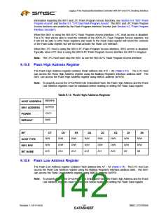
Table 9.10 DMS Register
N/A
HOST
ADDRESS
0x7F86
8051
ADDRESS
VCC1
0x00
POWER
DEFAULT
BIT
D7
D6
D5
D4
D3
D2
D1
D0
-
-
-
-
-
-
-
-
HOST TYPE
8051 R/W
R
R
R
R
R
R/WC
R/W
R/W
Reserved
DMS_
OVER
FLOW
DMS_TEST DMS_DISABLE
BIT NAME
9.9.4.1
9.9.4.2
DMS_OVERFLOW Bit – D2
The DMS_OVERFLOW bit indicates that the DMS overflow state has occurred (see Table 9.9, above).
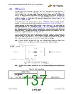
The DMS_OVERFLOW bit is the Carry output of the DMS counter (not shown in Figure 9.10).
When the DMS_OVERFLOW bit is deasserted ‘0’ (default), the DMS overflow state has not occurred or
has been cleared. When the DMS_OVERFLOW bit is asserted ‘1’, the DMS overflow state has
occurred. The DMS_OVERFLOW bit is R/WC. To deassert the DMS_OVERFLOW bit, write a ‘1’ to bit
D2. The DMS_OVERFLOW bit is also deasserted by VCC1 POR. The DMS_OVERFLOW bit can
inform the 8051 that an unprogrammed or corrupted Flash Boot Block has been restored without a
VCC1 POR.
DMS_TEST Bit – D1
The DMS_TEST bit along with the DMS_DISABLE bit (D0) can be used to exercise the DMS counter
and the nDMS_LED output pin for test purposes because in a properly functioning system the
DMS_LED output will never be asserted.
When the DMS_TEST bit is deasserted ‘0’ (default), the DMS test function is disabled. When the
DMS_TEST bit is asserted ‘1’, the DMS counter is cleared and disabled (Figure 9.10). The DMS_TEST
bit is R/W and deasserted by VCC1 POR. To exercise the nDMS_LED output pin, follow the steps shown
in Table 9.11.
Table 9.11 Exercising nDMS_LED Output Pin
ITEM #
PROCEDURE
DESCRIPTION
1
Deassert the DMS_DISABLE bit.
During normal boot procedure, the 8051 has
asserted the DMS_DISABLE bit before the
DMS overflow state has occurred. The
DMS_TEST bit must remain deasserted.
SMSC LPC47N350
121
Revision 1.1 (01-14-03)
DATASHEET

 SMSC [ SMSC CORPORATION ]