Legacy-Free Keyboard/Embedded Controller with SPI and LPC Docking Interface
nRESET = 0
STANDBY
nRESET = 1
CMD= FFh
CMD = C0h
CMD = B0h
READ
CMD = 20h
CMD = A0h
ARRAY
CMD= 80h CMD = 40h
CMD = 10h
SET MAIN
BLOCK
SET INFO
BLOCK
MASS
ERASE
PROGRAM
BYTE
PAGE
CLEAR
ERASE
STATUS
ACCESS
ACCESS
IDLE
(READ
STATUS)
CMD = 10h
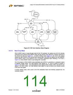
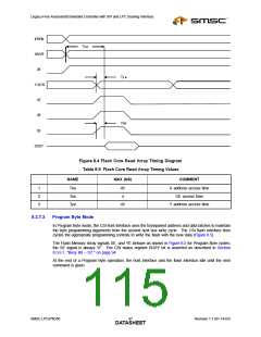
Figure 8.3 CSI Host Interface State Diagram
Read Array Mode
8.3.7.2
READ ARRAY mode is a pass-through mode for the CSI hardware: the address bus A[15:0] is directly
connected to the memory array address inputs and the memory array data bus is directly connected to
the DOUT[7:0] data bus (Figure 8.1). In READ ARRAY mode (Figure 8.4), the DOUT pins always
contain the valid contents of the selected flash memory 45 ns max after the address bus has stabilized.
READ ARRAY mode is the default for the LPC47N350 embedded flash following a CSI reset (
Figure 8.3). READ ARRAY mode is used during 8051 execution.
The CSI remains in READ ARRAY mode indefinitely until nRESET is asserted or a command is given
to explicitly change modes. The Flash Memory Array signals XE, YE, and SE behave as shown in
Figure 8.4 for READ cycles. The Flash Memory Array signals PROG, ERASE, MAS1 and NVSTR are
always ‘0’ for READ cycles. The Flash Memory Array signal OE may be driven by an inverted version
of the host read signal.
In READ ARRAY mode, write cycles to the 64k Embedded Flash Host Interface program the CSI
command register.
Revision 1.1 (01-14-03)
SMSC LPC47N350
DATA9S6HEET

 SMSC [ SMSC CORPORATION ]