Legacy-Free Keyboard/Embedded Controller with SPI and LPC Docking Interface
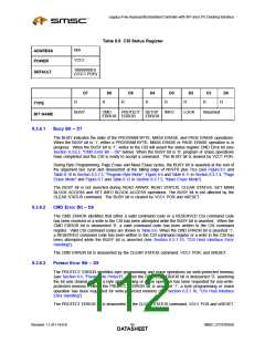
Table 8.8 CSI Status Register
N/A
ADDRESS
POWER
VCC1
‘00000X00’b
(VCC1 POR)
DEFAULT
D7
D6
D5
D4
D3
D2
D1
D0
R
R
R
R
R
R
R
R
TYPE
BUSY
CMD
PROTECT SETUP
ERROR
INFO
LOCK
Reserved
BIT NAME
ERROR ERROR
8.3.6.1
Busy Bit – D7
The BUSY indicates the state of the PROGRAM BYTE, MASS ERASE, and PAGE ERASE operations.
When the BUSY bit is ‘1’, either a PROGRAM BYTE, MASS ERASE or PAGE ERASE operation is in
progress. When the BUSY bit is ‘1’, writes to the CSI will assert the status register CMD Error bit (see
Section 8.3.6.2, "CMD Error Bit – D6" below). When the BUSY bit is ‘0’, program or erase operations
have completed and the CSI is ready to accept a command. The BUSY bit is cleared by VCC1 POR.
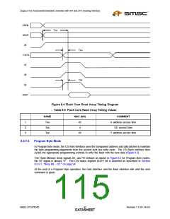
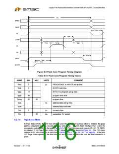
During Byte Programming, Page Erase and Mass Erase cycles, the BUSY bit is asserted at the end of
the argument bus cycle and deasserted at the falling edge of NVSTR plus Trcv (see Figure 8.5 and
Table 8.10 in Section 8.3.7.3, "Program Byte Mode", Figure 8.6 and Table 8.11 in Section 8.3.7.4, "Page
Erase Mode" and Figure 8.7 and Table 8.12 in Section 8.3.7.5, "Mass Erase Mode").
The BUSY bit is not asserted during READ ARRAY, READ STATUS, CLEAR STATUS, SET MAIN
BLOCK ACCESS and SET INFO BLOCK ACCESS operations. The BUSY bit is not affected by the
CLEAR STATUS command. The BUSY bit is cleared by VCC1 POR and nRESET.
8.3.6.2
8.3.6.3
CMD Error Bit – D6
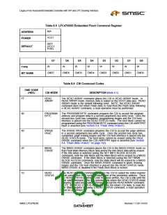
The CMD ERROR identifies that either a valid command code or a RESERVED CSI command code
has been received or a write to the CSI has been attempted while the BUSY bit is asserted. When the
CMD ERROR bit is deasserted ‘0’, a valid command code has been written to the CSI command
register. Valid CSI command codes are shown in Table 8.6. When the CMD ERROR bit is asserted ‘1’,
a RESERVED command code has been written to the CSI command register or a write to the CSI has
been attempted while the BUSY bit is asserted (see Section 8.3.7.10, "CSI Host Interface Error
Handling").
The CMD ERROR bit is deasserted by the CLEAR STATUS command, VCC1 POR, and nRESET.
Protect Error Bit – D5
The PROTECT ERROR identifies byte programming and erase operations on write-protected memory
(see Section 8.4, "Flash Write Protect"). When the PROTECT ERROR bit is deasserted ‘0’, assuming
the bit was cleared initially, a byte programming or erase operation has been requested for non-write-
protected memory. When the PROTECT ERROR bit is asserted ‘1’, a byte programming or erase
operation has been requested for write-protected memory (see Section 8.3.7.10, "CSI Host Interface
Error Handling").
The PROTECT ERROR bit is deasserted by the CLEAR STATUS command, VCC1 POR and nRESET.
Revision 1.1 (01-14-03)
SMSC LPC47N350
DATA9S4HEET

 SMSC [ SMSC CORPORATION ]