Legacy-Free Keyboard/Embedded Controller with SPI and LPC Docking Interface
Table 8.7 CSI Command Types and Bus Cycles (continued)
COMMAND CODE CYCLE
ARGUMENT CYCLE
COMMAND
TYPE
NOTES
OPERATION
WRITE
ADDRESS
DATA
OPERATION ADDRESS
DATA
ERASE
PAGE
2
X
40H
WRITE
PGA
X
Note 8.4
,
Note 8.6
,
Note 8.7
MASS
1
1
1
1
1
20H
10H
A0H
B0H
C0H
-
-
-
-
-
-
-
-
-
-
-
-
-
-
-
Note 8.6
,
ERASE
Note 8.7
READ
Note 8.6
,
STATUS
Note 8.7
CLEAR
Note 8.6
,
STATUS
Note 8.7
SET MAIN
BLOCK
Note 8.6
,
ACCESS
Note 8.7
SET INFO
BLOCK
Note 8.6
,
ACCESS
Note 8.7
Note 8.2 PRA = Program Address
Note 8.3 PRD = Program Data
Note 8.4 PGA = Page Address
Note 8.5 SRD = Status Register Data
Note 8.6 The CSI is IDLE following this command
Note 8.7 X = Don’t Care
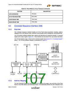
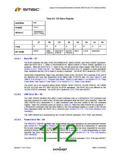
8.3.6
Status Register
The CSI status register displays the working state of Command Sequence Interface hardware
(Figure 8.2). The status register is read-only and is set to ‘00000X00’b by default (Table 8.8). Note that
status register bit D2 always reflects the state of the CSI nWRTPRT input (see Section 8.3.6.6, "Lock
Bit – D2" below).
The CSI Status register is cleared by the CLEAR STATUS command, VCC1 POR and nRESET.
APPLICATION NOTE: Asserted CSI status register error bits must be deasserted using the CLEAR STATUS
command before executing subsequent CSI commands.
SMSC LPC47N350
Revision 1.1 (01-14-03)
DATA9S3HEET

 SMSC [ SMSC CORPORATION ]