Legacy-Free Keyboard/Embedded Controller with SPI and LPC Docking Interface
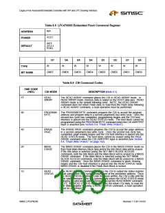
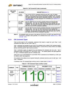
Table 8.6 CSI Command Codes (continued)
CMD CODE
(HEX)
CSI MODE
DESCRIPTION (Note 8.1)
A0
CLEAR
The CLEAR STATUS command resets the error bits in the CSI Status
register. Once the CLEAR STATUS command has completed, the CSI is idle
and in the Read Status mode until the next valid command. NOTE: asserted
CSI Status register error bits must be deasserted using the CLEAR STATUS
command before executing subsequent CSI commands (see Section 8.3.6,
"Status Register").
STATUS
B0
C0
SET MAIN
BLOCK
The SET MAIN BLOCK ACCESS command selects the 64k-byte Main
Memory Block. Once the SET MAIN BLOCK ACCESS command has
completed, the CSI is idle and in the Read Status mode until the next valid
command. All subsequent commands apply to the Main Block until the SET
INFO BLOCK ACCESS command is specified.
ACCESS
SET INFO
BLOCK
The SET INFO BLOCK ACCESS command selects the 128-byte Information
Memory Block. Once the SET INFO BLOCK ACCESS command has
completed, the CSI is idle and in the Read Status mode until the next valid
command. All subsequent commands apply to the Information Block until the
SET MAIN BLOCK ACCESS command is specified.
ACCESS
Note 8.1 All command codes not shown in this table are RESERVED by SMSC and cannot be used.
RESERVED command codes generate CSI command errors (see Section 8.3.6.2, "CMD
Error Bit – D6").
8.3.5
CSI Command Types
There are two types of CSI commands: commands that require a single bus cycle (Type 1) and
commands that require two bus cycles (Type 2).
Type 1 commands are executed as soon as the CSI command code is written to the command register.
Type 1 commands include READ ARRAY, MASS ERASE, CLEAR STATUS, READ STATUS, SET MAIN
BLOCK ACCESS and SET INFO BLOCK ACCESS.
Type 2 commands require an argument bus cycle following the command code bus cycle. Type 2
commands include PROGRAM BYTE, and ERASE PAGE. The required address and data arguments
for Type 2 commands depends upon the command code.
Setup errors occur if PROGRAM BYTE and ERASE PAGE commands are not followed by a write cycle
for address and/or data arguments.
The contents of the address bus are ignored during the command code bus cycle for both Type 1 and
Type 2 commands.
A summary of the CSI command types and bus cycles is shown below in Table 8.7.
Table 8.7 CSI Command Types and Bus Cycles
COMMAND CODE CYCLE
ARGUMENT CYCLE
COMMAND
TYPE
NOTES
OPERATION
WRITE
ADDRESS
DATA
OPERATION ADDRESS
DATA
READ
1
2
X
FFH
-
-
-
Note 8.7
ARRAY
PROGRAM
BYTE
80H
WRITE
PRA
PRD
Note 8.2
,
Note 8.3
,
Note 8.6
,
Note 8.7
Revision 1.1 (01-14-03)
SMSC LPC47N350
DATA9S2HEET

 SMSC [ SMSC CORPORATION ]