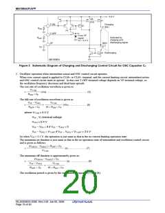
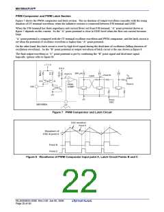
M51995AP/AFP
+
+
M51995A
M51995A
VOUT
CLM+
GND
VOUT
GND
RNF
CNF
RCLM
CNF
RCLM
CLM−
RNF
(b) In case of CLM−
(a) In case of CLM+
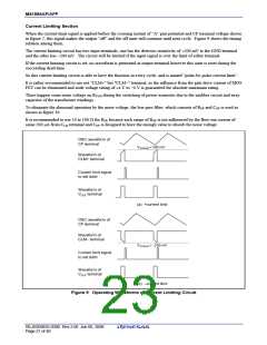
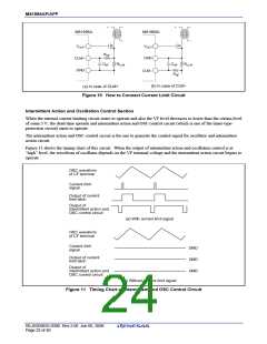
Figure 10 How to Connect Current Limit Circuit
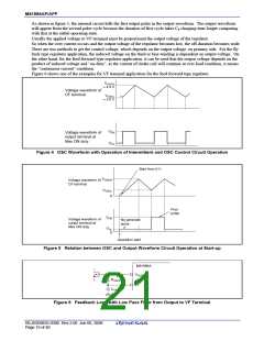
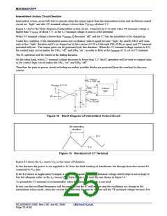
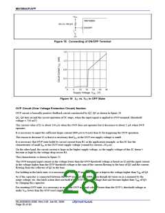
Intermittent Action and Oscillation Control Section
When the internal current limiting circuit states to operate and also the VF level decreases to lower than the certain level
of some 3 V, the dead-time spreads and intermittent action and OSC control circuit (which is one of the timer-type-
protection circuit) starts to operate.
The intermittent action and OSC control circuit is the one to generate the control signal for oscillator and intermittent
action circuit.
Figure 11 shows the timing-chart of this circuit. When the output of intermittent action and oscillation control is at
“high” level, the waveform of oscillator depends on the VF terminal voltage and the intermittent action circuit begins to
operate.
OSC waveform
of CF terminal
Current limit
signal
Output of current
limit latch
Output of
intermittent action and
OSC control circuit
(a) With current limit signal
OSC waveform
of CF terminal
Current limit
signal
GND
Output of current
limit latch
GND
Output of
intermittent action and
OSC control circuit
GND
(b) Without current limit signal
Figure 11 Timing Chart of Intermittent and OSC Control Circuit
REJ03D0835-0300 Rev.3.00 Jun 06, 2008
Page 22 of 40

 RENESAS [ RENESAS TECHNOLOGY CORP ]