M51995AP/AFP
Intermittent Action Circuit Section
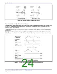
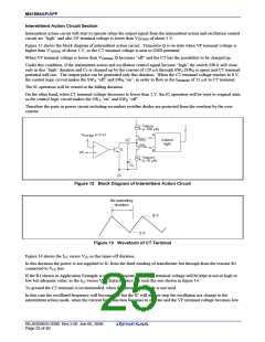
Intermittent action circuit will start to operate when the output signal from the intermittent action and oscillation control
circuit are “high” and also VF terminal voltage is lower than VTHTIME of about 3 V.
Figure 12 shows the block diagram of intermittent action circuit. Transistor Q is on state when VF terminal voltage is
higher than VTHTIME of about 3 V, so the CT terminal voltage is near to GND potential.
When VF terminal voltage is lower than VTHTIME, Q becomes “off” and the CT has the possibility to be charged up.
Under this condition, if the intermittent action and oscillation control signal become “high” the switch SWA will close
only in this “high” duration and CT is charged up by the current of 120 µA through SWA (SWB is open) and CT terminal
potential will rise. The output pulse can be generated only this duration. When the CT terminal voltage reaches to 8 V,
the control logic circuit makes the SWA “off” and SWB “on”, in order to flow in the ITIMEOFF of 15 µA to CT terminal.
The IC operation will be ceased in the falling duration.
On the other hand, when CT terminal voltage decreases to lower than 2 V, the IC operation will be reset to original state,
as the control logic circuit makes the SWA “on” and SWB “off”.
Therefore the parts in power circuit including secondary rectifier diodes are protected from the overheat by the over
current.
ITIMEON
(≈ 120 µA)
VTHTIME (≈ 3 V)
A
SWA
SWB
CT
Control
logic
−
Q
B
VF
+
ITIMEOFF
(≈ 15 µA)
+
CT
Figure 12 Block Diagram of Intermittent Action Circuit
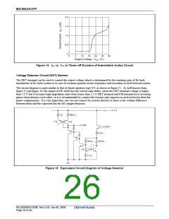
No operating
duration
8 V
2 V
Figure 13 Waveform of CT Terminal
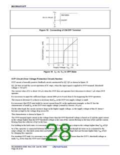
Figure 14 shows the ICC versus VCC in this timer-off duration.
In this duration the power is not supplied to IC from the third winding of transformer but through from the resistor R1
connected to VCC line.
If the R1 shown in Application Example is selected adequate value, VCC terminal voltage will be kept at not so high or
low but adequate value, as the ICC versus VCC characteristics has such the one shown in figure 14.
To ground the CT terminal is recommended, when the intermittent mode is not used.
In this case the oscillated frequency will become low but the IC will neither stop the oscillation nor change to the
intermittent action mode, when the current limit function becomes to operate and the VF terminal voltage becomes low.
REJ03D0835-0300 Rev.3.00 Jun 06, 2008
Page 23 of 40

 RENESAS [ RENESAS TECHNOLOGY CORP ]