3858 Group
Electrical characteristics
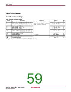
Absolute maximum ratings
Table 7 Absolute maximum ratings
Symbol
Parameter
Conditions
Ratings
–0.3 to 6.5
Unit
V
VCC
Power source voltage
All voltages are based on VSS.
Input voltage P00–P07, P10–P17, P20, P21,
P24–P27, P30–P34, P40–P44,
VREF
When an input voltage is measured,
output transistors are cut off.
V
VI
–0.3 to VCC +0.3
Input voltage P22, P23
Input voltage RESET, XIN
Input voltage CNVSS
–0.3 to VCC +0.3
–0.3 to VCC +0.3
–0.3 to 8.0
VI
V
V
V
V
VI
VI
Output voltage P00–P07, P10–P17, P20, P21,
P24–P27, P30–P34, P40–P44,
XOUT
–0.3 to VCC +0.3
VO
Output voltage P22, P23
Power dissipation
–0.3 to 5.8
1000 (Note)
–20 to 85
VO
V
mW
°C
Pd
Ta = 25 °C
Operating temperature
Storage temperature
Topr
Tstg
–40 to 125
°C
Note : The rating becomes 300mW at the PRSP0042GA-B (42P2R-A/E) package.
Rev.1.10 Apr 3, 2006 page 59 of 75
REJ03B0139-0110

 RENESAS [ RENESAS TECHNOLOGY CORP ]