3858 Group
(2) Wait mode
CLOCK GENERATING CIRCUIT
If the WIT instruction is executed, the internal clock φ stops at an
“H” level, but the oscillator does not stop. The internal clock φ re-
starts at reset or when an interrupt is received. Since the oscillator
does not stop, normal operation can be started immediately after
the clock is restarted.
The 3858 group has two built-in oscillation circuits. An oscillation cir-
cuit can be formed by connecting a resonator between XIN and XOUT
(XCIN and XCOUT). Use the circuit constants in accordance with the
resonator manufacturer’s recommended values. No external resistor
is needed between XIN and XOUT since a feed-back resistor exists
on-chip.(An external feed-back resistor may be needed depending on
conditions.) However, an external feed-back resistor is needed be-
tween XCIN and XCOUT.
To ensure that the interrupts will be received to release the STP or
WIT state, their interrupt enable bits must be set to “1” before ex-
ecuting of the STP or WIT instruction.
Immediately after power on, only the XIN oscillation circuit starts oscil-
lating, and XCIN and XCOUT pins function as I/O ports.
When releasing the STP state, the prescaler 12 and timer 1 will
start counting the clock XIN divided by 16. Accordingly, set the timer
1 interrupt enable bit to “0” before executing the STP instruction.
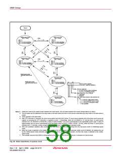
• Frequency Control
(1) Middle-speed mode
The internal clock φ is the frequency of XIN divided by 8. After re-
■Notes
• If you switch the mode between middle/high-speed and low-
speed, stabilize both XIN and XCIN oscillations. The sufficient
time is required for the sub-clock to stabilize, especially immedi-
ately after power on and at returning from the stop mode. When
switching the mode between middle/high-speed and low-speed,
set the frequency on condition that f(XIN) > 3 × f(XCIN).
• When using the oscillation stabilizing time set after STP instruction
released bit set to “1”, evaluate time to stabilize oscillation of the
used oscillator and set the value to the timer 1 and prescaler 12.
set is released, this mode is selected.
(2) High-speed mode
The internal clock φ is half the frequency of XIN.
(3) Low-speed mode
The internal clock φ is half the frequency of XCIN.
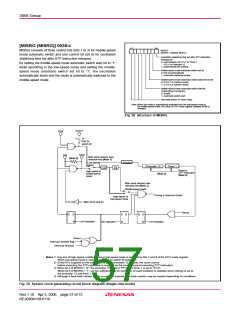
(4) Low power dissipation mode
The low power consumption operation can be realized by stopping
the main clock XIN in low-speed mode. To stop the main clock, set
bit 5 of the CPU mode register to “1”. When the main clock XIN is
restarted (by setting the main clock stop bit to “0”), set sufficient
time for oscillation to stabilize.
The sub-clock XCIN-XCOUT oscillating circuit can not directly input
clocks that are generated externally. Accordingly, make sure to
cause an external resonator to oscillate.
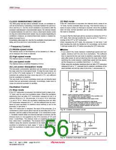
X
CIN
X
COUT
X
IN
X
OUT
Rd (Note)
Rf
Rd
Oscillation Control
C
OUT
C
CIN
C
COUT
CIN
(1) Stop mode
If the STP instruction is executed, the internal clock φ stops at an
“H” level, and XIN and XCIN oscillation stops. When the oscillation
stabilizing time set after STP instruction released bit (bit 0 of
address 003816) is “0”, the prescaler 12 is set to “FF16” and timer
1 is set to “0116”. When the oscillation stabilizing time set after
STP instruction released bit is “1”, set the sufficient time for oscil-
lation of used oscillator to stabilize since nothing is set to the
prescaler 12 and timer 1.
Notes : Insert a damping resistor if required.
The resistance will vary depending on the oscillator and
the oscillation drive capacity setting.
Use the value recommended by the maker of the
oscillator.
Also, if the oscillator manufacturer's data sheet
specifies that a feedback resistor be added external to
the chip though a feedback resistor exists on-chip,
insert a feedback resistor between XIN and XOUT
following the instruction.
After STP instruction is released, the input of the prescaler 12 is
connected to count source which had set at executing the STP in-
struction, and the output of the prescaler 12 is connected to timer
1. Oscillator restarts when an external interrupt is received, but the
internal clock φ is not supplied to the CPU (remains at “H”) until
timer 1 underflows. The internal clock φ is supplied for the first
time, when timer 1 underflows. This ensures time for the clock os-
cillation using the ceramic resonators to be stabilized. When the
oscillator is restarted by reset, apply “L” level to the RESET pin
until the oscillation is stable since a wait time will not be gener-
ated.
Fig. 56 Ceramic resonator circuit
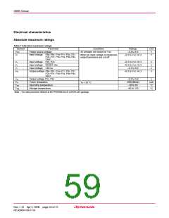
XCIN
X
COUT
XIN
XOUT
Open
Rf
Rd
External oscillation
circuit
C
CIN
CCOUT
Vcc
Vss
Fig. 57 External clock input circuit
Rev.1.10 Apr 3, 2006 page 56 of 75
REJ03B0139-0110

 RENESAS [ RENESAS TECHNOLOGY CORP ]