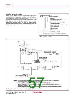
3858 Group
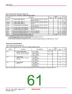
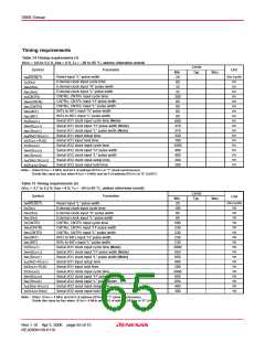
Table 9 Recommended operating conditions (2)
(VCC = 2.7 to 5.5 V, Ta = –20 to 85 °C, unless otherwise noted)
Limits
Typ.
Symbol
Parameter
Unit
mA
Min.
Max.
I
OH(peak)
“H” output voltage (Note 1)
P00–P07, P10–P17, P20, P21, P24–P27,
P30–P34, P40–P44
–10
IOL(peak)
IOL(peak)
IOH(avg)
“L” output voltage (Note 1)
“L” output voltage (Note 1)
“H” average output current (Note 2)
P00–P07, P20–P27, P30–P34, P40–P44
P10–P17
mA
mA
mA
10
20
–5
P00–P07, P10–P17, P20, P21, P24–P27,
P30–P34, P40–P44
I
OL(avg)
OL(avg)
“L” average output current (Note 2)
“L” average output current (Note 2)
P00–P07, P20–P27, P30–P34, P40–P44
P10–P17
mA
mA
5
I
15
f(XIN
)
)
Internal clock oscillation frequency (VCC = 4.0 to 5.5V) (Note 3)
Internal clock oscillation frequency (VCC = 2.7 to 4.0V) (Note 3)
Sub-clock input oscillation frequency (Note 3, 4)
MHz
MHz
kHz
12.5
f(XIN
5VCC–7.5
f(XCIN
)
50
32.768
Note 1: The peak output current is the peak current flowing in each port.
2: The average output current IOL (avg), IOH (avg) in an average value measured over 100 ms.
3: When the oscillation frequency has a duty cycle of 50 %.
4: When using the microcomputer in low-speed mode, set the sub-clock input oscillation frequency on condition that f(XCIN) < f(XIN)/3.
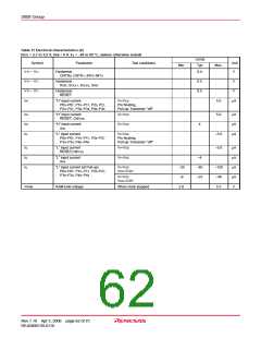
Electrical characteristics
Table 10 Electrical characteristics (1)
(VCC = 2.7 to 5.5 V, VSS = 0 V, Ta = –20 to 85 °C, unless otherwise noted)
Limits
Symbol
Parameter
Unit
V
Test conditions
Min.
Typ.
Max.
“H” output voltage (Note)
VOH
VOL
VOL
IOH = –10mA
VCC – 2.0
P00–P07, P10–P17, P20, P21
P24–P27, P30–P34, P40–P44
VCC=4.0–5.5V
IOH = –1.0mA
VCC=2.7–5.5V
VCC – 1.0
V
V
V
V
V
“L” output voltage
P00–P07, P20–P27, P30–P34
P40–P44
IOL = 10mA
VCC=4.0–5.5V
2.0
1.0
2.0
1.0
IOL = 1.0mA
VCC=2.7–5.5V
“L” output voltage
P10–P17
IOL = 20mA
VCC=4.0–5.5V
IOL = 10mA
VCC=2.7–5.5V
Note: P25 is measured when the P25/TXD P-channel output disable bit of the UART control register (bit 4 of address 001B16) is “0”.
Rev.1.10 Apr 3, 2006 page 61 of 75
REJ03B0139-0110

 RENESAS [ RENESAS TECHNOLOGY CORP ]