3858 Group
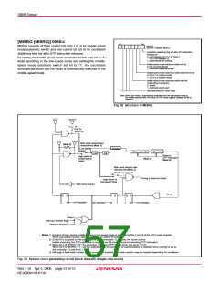
[MISRG (MISRG)] 003816
b0
b7
MISRG
(MISRG : address 003816
MISRG consists of three control bits (bits 1 to 3) for middle-speed
mode automatic switch and one control bit (bit 0) for oscillation
stabilizing time set after STP instruction released.
)
Oscillation stabilizing time set after STP instruction
released bit
0: Automatically set “0116” to Timer 1,
“FF16” to Prescaler 12
By setting the middle-speed mode automatic switch start bit to “1”
while operating in the low-speed mode and setting the middle-
speed mode automatic switch set bit to “1”, XIN oscillation
automatically starts and the mode is automatically switched to the
middle-speed mode.
1: Automatically set nothing
Middle-speed mode automatic switch set bit
0: Not set automatically
1: Automatic switching enable
Middle-speed mode automatic switch wait time set bit
0: 6.5 to 7.5 machine cycles
1: 4.5 to 5.5 machine cycles
Middle-speed mode automatic switch start bit
(Depending on program)
0: Invalid
1: Automatic switch start
Not used (return “0” when read)
Note: When the mode is automatically switched from the low-speed mode to
the middle-speed mode, the value of CPU mode register (address 003B16
changes.
)
Fig. 58 Structure of MISRG
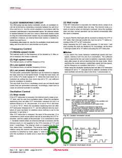
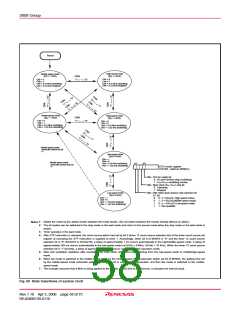
X
COUT
XCIN
“0”
“1”
Port X
C
switch bit
X
OUT
X
IN
Main clock division ratio
selection bits (Note 1)
(Note 4)
Low-speed
mode
Divider
Prescaler 12
(Note 3)
Timer 1
1/2
1/4
Reset or
STP instruction
(Note 2)
High-speed or
middle-speed
mode
Main clock division ratio
selection bits (Note 1)
Middle-speed mode
Timing φ (internal clock)
High-speed or
low-speed mode
Main clock stop bit
Reset
Q
S
R
S
R
Q
Q
S
R
STP instruction
STP instruction
WIT instruction
Reset
Interrupt disable flag l
Interrupt request
Notes 1: Any one of high-speed, middle-speed or low-speed mode is selected by bits 7 and 6 of the CPU mode register.
When low-speed mode is selected, set port Xc switch bit (b4) to “1”.
2: f(XIN)/16 is supplied as the count source to the prescaler 12 at reset, the count source
before executing the STP instruction is supplied as the count source at executing STP instruction.
3: When bit 0 of MISRG = “0”, the prescaler 12 is set to "FF16" and timer 1 is set to "0116".
When bit 0 of MISRG = “1”, set the sufficient time for oscillation of used oscillator to stabilize since nothing is set to
the prescaler 12 and timer 1.
4: Although a feed-back resistor exists on-chip, an external feed-back resistor may be needed depending on conditions.
Fig. 59 System clock generating circuit block diagram (Single-chip mode)
Rev.1.10 Apr 3, 2006 page 57 of 75
REJ03B0139-0110

 RENESAS [ RENESAS TECHNOLOGY CORP ]