3858 Group
RESET CIRCUIT
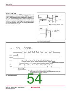
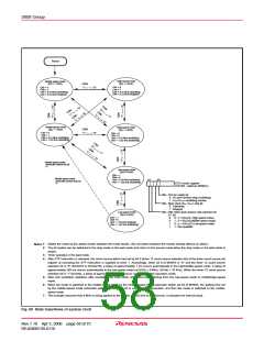
To reset the microcomputer, RESET pin must be held at an “L”
level for 20 cycles or more of XIN. Then the RESET pin is returned
to an “H” level (the power source voltage must be between 2.7 V
and 5.5 V, and the oscillation must be stable), reset is released.
After the reset is completed, the program starts from the address
contained in address FFFD16 (high-order byte) and address
FFFC16 (low-order byte). Make sure that the reset input voltage is
less than 0.54 V for VCC of 2.7 V.
Poweron
(Note)
Power source
voltage
0V
RESET
VCC
Reset input
voltage
0V
0.2VCC
Note : Reset release voltage; Vcc = 2.7 V
RESET
VCC
Power source
voltage detection
circuit
Fig. 53 Reset circuit example
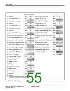
X
IN
φ
RESET
RESETOUT
Address
AD
H,L
?
?
?
?
FFFC
FFFD
Reset address from the vector table.
AD
H
Data
?
?
?
AD
L
?
SYNC
X
IN: 8 to 13 clock cycles
Notes1: The frequency relation of f(XIN) and f(φ) is f(XIN) = 2 • f(φ).
2: The question marks (?) indicate an undefined state that depends on the previous state.
3: All signals except XIN and RESET are internals.
Fig. 54 Reset sequence
Rev.1.10 Apr 3, 2006 page 54 of 75
REJ03B0139-0110

 RENESAS [ RENESAS TECHNOLOGY CORP ]