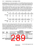
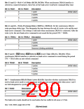
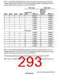
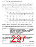
Bit 15—Area 6 Wait Control (A6W3): Specifies the number of inserted wait states for area 6
combined with bits A6W2–A6W0 in WCR2. Also specifies the number of transfer states in burst
transfer. Clear this bit to 0 when area 6 is not set to PCMCIA.
First Cycle
Burst Cycle
Number of
States per
One-data
Transfer
Inserted Wait
States
A6W3
A6W2
A6W1
A6W0
WAIT Pin
Ignored
Enabled
Enabled
Enabled
Enabled
Enabled
Enabled
Enabled
WAIT Pin
Enabled
Enabled
Enabled
Enabled
Enabled
Enabled
Enabled
Enabled
0
0
0
0
0
0
0
0
0
0
0
0
1
1
1
1
0
0
1
1
0
0
1
1
0
1
0
1
0
1
0
1
0
1
2
3
4
6
8
2
2
3
4
5
7
9
10
11
(Initial value)
1
1
1
1
1
1
1
1
0
0
0
0
1
1
1
1
0
0
1
1
0
0
1
1
0
1
0
1
0
1
0
1
12
14
18
22
26
30
34
38
Enabled
Enabled
Enabled
Enabled
Enabled
Enabled
Enabled
Enabled
13
15
19
23
27
31
35
39
Enabled
Enabled
Enabled
Enabled
Enabled
Enabled
Enabled
Enabled
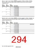
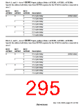
Bit 14—Area 5 Wait Control (A5W3): Specifies the number of inserted wait states for area 5
combined with bits A5W2–A5W0 in WCR2. Also specifies the number of transfer states in burst
transfer. Clear this bit to 0 when area 5 is not set to PCMCIA.
The relationship between the set value and the number of waits is the same as for A6W3.
Bits 13 and 12—Reserved: These bits are always read as 0. The write value should always be 0.
Rev. 5.00, 09/03, page 249 of 760

 RENESAS [ RENESAS TECHNOLOGY CORP ]