PM6341 E1XC
DATA SHEET
PMC-910419
ISSUE 8
E1 FRAMER/TRANSCEIVER
Data Register is the last byte in a frame (due to an end-of-message or an abort),
or an overrun condition occurs, then the RDLEOM output goes high. The DMA
controller is inhibited from reading any more bytes, and the processor is
interrupted. The processor can then halt the DMA controller, read the Status
Register, process the frame, and finally reset the DMA controller to process the
data for the next frame.The RDLEOM output can optionally be enabled to
generate a processor interrupt through the common INTB output via the
RDLEOME bit in the Datalink Options register, rather than tying the RDLEOM
output directly to the microprocessor.This allows a central microprocessor
controlling the E1XC operation to also respond to conditions affecting the DMA
servicing of RFDL. When using the INTB output, the central processor must poll
the Interrupt ID/Clock Monitor, and the Interrupt Source Registers to identify the
source of the interrupt before beginning any interrupt service routine.
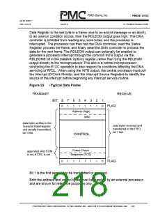
Figure 22
-Typical Data Frame
TRANSMIT
RECEIVE
BIT: 8
7
6
5
4
3
2
1
0
1
1
1
1
1
1
0
FLAG
Address (high)
(low)
data bytes written to the
Transmit Data Register
and serially transmitted,
bit 1 first
data bytes received and
transferred to the FIFO,
bit 1 first
CONTROL
Frame Check
appended after EOM
is set, if CRC is set
Sequence (FCS)
0
1
1
1
1
1
1
0
FLAG
Bit 1 is the first serial bit to be transmitted or received.
Both the address and control bytes must be supplied by an external processor
and are shown for reference purposes only.
PROPRIETARY AND CONFIDENTIAL TO PMC-SIERRA, INC., AND FOR ITS CUSTOMERS’ INTERNAL USE
202

 PMC [ PMC-SIERRA, INC ]