PM6341 E1XC
DATA SHEET
PMC-910419
ISSUE 8
E1 FRAMER/TRANSCEIVER
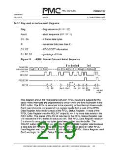
RFDL will ignore the entire frame including the abort sequence (since it has not
occurred in a valid frame or during flag reception, according to the RFDL).
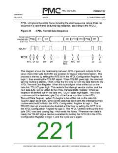
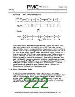
Figure 25
- XFDL Normal Data Sequence
Serial Data
inserted into
ESF FDL
CRC1 CRC2
Flag D1
D2
Dn
Flag D1
TDLINT
D[7:0]
INTE D1 D2
D3
D4
EOM
INTE
INTE D1
D2
D3
This diagram shows the relationship between XFDL inputs and outputs for the
case where interrupts and CRC are enabled for regular data transmission. The
process is started by setting the INTE bit in the XFDL Configuration Register to
logic 1, thus enabling the TDLINT signal. When TDLINT goes high, the interrupt
service routine is started, which writes the first byte (D1) of the data frame to the
XFDL Transmit Data Register. When this byte begins to be shifted out on the
data link, TDLINT goes high. This restarts the interrupt service routine, and the
next data byte (D2) is written to the XFDL Transmit Data Register. When D2
begins to be shifted out on the data link, TDLINT goes high again. This cycle
continues until the last data byte (Dn) of the frame is written to the XFDL
Transmit Data Register. When Dn begins to be shifted out on the data link,
TDLINT again goes high. Since all the data has been sent, the interrupt service
routine sets the EOM bit in the XFDL Configuration Register to logic 1. The
TDLINT interrupt should also be disabled at this time by setting the INTE bit in
the XFDL Configuration Register to logic 0. The XFDL will then shift out the two-
byte CRC word and closing flag, which ends the frame. Whenever new data is
ready, the TDLINT signal can be re-enabled by setting the INTE bit in the XFDL
Configuration Register to logic 1, and the cycle starts again.
PROPRIETARY AND CONFIDENTIAL TO PMC-SIERRA, INC., AND FOR ITS CUSTOMERS’ INTERNAL USE
205

 PMC [ PMC-SIERRA, INC ]