PM6341 E1XC
DATA SHEET
PMC-910419
ISSUE 8
E1 FRAMER/TRANSCEIVER
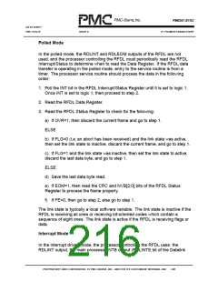
The RDLEOM output goes high as soon as the last byte in the frame is read from
the RFDL Data Register. The RDLINT output will go low if the FIFO buffer is
empty. The next RFDL Status Register read will return a value of logic 1 for the
EOM and FLG bits, and cause the RDLEOM output of the RFDL to return low.
In the next frame, the first data byte is received, and after a delay of ten bit
periods, it is written to the FIFO buffer, and read by the processor after the
interrupt. When the abort sequence is detected, the data received up to the
abort is written to the FIFO buffer and an interrupt generated. The processor
then reads the partial byte from the RFDL Data Register and the RDLEOM
output is set high. The processor then reads the RFDL Status Register which will
return a value of logic 1 for the EOM and FLG bits, and set the RDLEOM output
low. The FIFO buffer is not cleared when an abort is detected. All bytes received
up to the abort are available to be read.
After an abort, the RFDL state machine will be in the receiving all ones state,
and the data link status will be idle. When the first flag is detected, a new
interrupt will be generated, with a dummy data byte loaded into the FIFO buffer,
to indicate that the data link is now active.
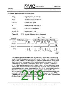
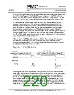
Figure 24
- RFDL FIFO Overrun
B1 B2 B3
Serial Data
extracted from
ESF FDL
Flag D1 D2 D3
Dn-1 Dn R C1 C2 Flag D1 R Abort
RDLINT
RDLEOM
D[7:0]
D1D2
STATUSRD
OVR
This diagram shows the relationship between RFDL inputs and outputs for the
case where interrupts are programmed to occur when two data bytes are present
in the FIFO buffer. Each read is composed of two register reads, as described
above. In this example, data is not read by the end of B2. An overrun occurs
since unread data (Dn-3) has been overwritten by B1. This sets the RDLEOM
output high, and resets both the RFDL and the FIFO buffer. The RFDL is held
disabled until the RFDL Status Register is read. The start flag sequence is not
detected since the RFDL is still held disabled when it occurs. Consequently, the
PROPRIETARY AND CONFIDENTIAL TO PMC-SIERRA, INC., AND FOR ITS CUSTOMERS’ INTERNAL USE
204

 PMC [ PMC-SIERRA, INC ]