PM6341 E1XC
DATA SHEET
PMC-910419
ISSUE 8
E1 FRAMER/TRANSCEIVER
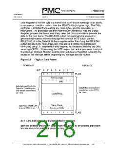
14.3.1 Key used on subsequent diagrams:
Flag
- flag sequence (01111110)
Abort
- abort sequence (01111111)
- n frame data bytes
D1 - Dn
R
- remainder bits (less than 8)
- CRC-CCITT information
C1, C2
B1, B2, B3
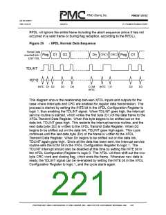
Figure 23
- groupings of 8 bits
- RFDL Normal Data and Abort Sequence
B1 B2 B3
B1
Serial Data
Flag D1 D2 D3
Dn-1 Dn
Flag
Abort
R
extracted from
ESF FDL
R
C1 C2
D1
RDLINT
RDLEOM
D[7:0]
Dn-1
Dn-3 Dn-2
D1 D2
Dn B1 B2 B3
EOM
D1 B1
ABORT
EOM
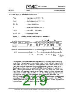
This diagram shows the relationship between RFDL inputs and outputs for the
case where interrupts are programmed to occur when one byte is present in the
FIFO buffer. The RFDL is assumed to be operating in the interrupt driven mode.
Each read shown is composed of two register reads: first a read of the RFDL
Data Register, followed by a read of the RFDL Status Register. A read of the
RFDL Data Register sets the RDLINT output to low if no more data exists in the
FIFO buffer. The status of the FE bit returned in the RFDL Status Register read
will indicate the FIFO buffer fill status as well. The RFDL Data Register read Dn-
2 is shown to occur after two bytes have been written into the buffer. The
RDLINT output does not go low after the first RFDL Data Register read because
a data byte still remains to be read. The RDLINT output goes low after RFDL
Data Register read Dn-1. The FE bit will be logic 0 in RFDL Status Register read
Dn-2 and logic 1 in RFDL Status Register read Dn-1.
PROPRIETARY AND CONFIDENTIAL TO PMC-SIERRA, INC., AND FOR ITS CUSTOMERS’ INTERNAL USE
203

 PMC [ PMC-SIERRA, INC ]