Performance Metrics
PLX Technology, Inc.
Egress Port Arbitration
Regarding egress ports, the PEX 8532 supports only one port arbitration mechanism – non-configurable
hardware arbitration scheme. In particular, the oldest ready packet from all ingress ports arriving at the
current egress port are selected first. Ready packet is defined as a packet with available egress credit and
no ordering violations.
8.4
Throughput
8.4.1
Theoretical Upper Limit
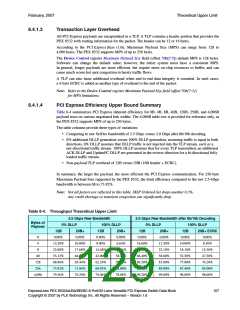
PCI Express allows for bi-directional traffic capability and scalable widths, allowing it to closely match
the necessary bandwidth. As discussed in this section, compared to the 2.5-Gbps raw bandwidth
provided by each SerDes lane, the achievable data payload efficiency, assume the Maximum Payload
Size (MPS) of 256B is approximately 70ꢀ.
8.4.1.1
Physical Layer Overhead
The 2.5-Gbps serial data on a SerDes is encoded with additional information for clock recovery and
error detection through 8b/10b encoding. When the additional information is removed, a 2.0-Gbps data
rate remains, which is 80ꢀ of the starting bandwidth.
The PHY Layer also adds a 1-byte start symbol (STP) and a 1-byte end symbol (END or EDB) to the
packet size, thereby introducing 2 bytes of overhead per TLP.
Also in the PHY Layer, SKIP Ordered-Sets are used to compensate for differences in frequency between
bit rates at opposite ends of a Link. The PCI Express Base r1.0a specifies a clock frequency tolerance of
600 parts per million (ppm), which in turn requires a SKIP Ordered-Sets to transmit within the range of
1,180 to 1,530 symbol times. This causes the achievable efficiency to drop another 4/1,180 = 0.34ꢀ.
8.4.1.2
Data Link Layer Overhead
To ensure data integrity passing over the wire, the PCI Express Base r1.0a states that the DLL (Data
Link Layer) adds a sequence number at the start of the packet and an LCRC integrity check at the end of
the packet. The sequence number is 2 bytes, and the LCRC is 4 bytes, thereby introducing 6 bytes of
overhead per TLP.
In addition to the overhead inherent in TLP payload transmission, the PCI Express Base r1.0a uses the
same wire to transmit DLLPs (Data Link Layer Packets). ACK (acknowledge) and UpdateFC are the
two most frequently used types of DLLPs during standard run time, where throughput matters. ACK is
used to acknowledge TLP receipt. UpdateFC is used to provide additional credits, which enables
additional TLP transactions.
DLLPs are structured so that a single ACK can represent receiving multiple TLPs, reducing the total
number of ACKs required. Similarly, a single UpdateFC is structured so that credit for more than one
packet can be extended at a time, reducing the number of required UpdateFCs per TLP. The size of a
single DLLP is 8 bytes. In the worst case, two outgoing DLLPs are formed for each incoming TLP,
which equals 16B in per TLP overhead. In the best case, there is zero DLLP overhead for incoming
TLPs. DLLPs flow in the opposite direction of TLPs, as they are feedback mechanisms. For one-way
TLP traffic, the DLLP overhead does not impact overall link utilization.
106
ExpressLane PEX 8532AA/BA/BB/BC 8-Port/32-Lane Versatile PCI Express Switch Data Book
Copyright © 2007 by PLX Technology, Inc. All Rights Reserved – Version 1.6

 PLX [ PLX TECHNOLOGY ]