Philips Semiconductors
Preliminary specification
Stereo audio codec with SPDIF interface
UDA1355H
Table 8 Muting to prevent plopping
BIT
OCCASION
DE-MUTE CONDITION
MT1
MT2
MTM
Input selection
Select channel 1 source
Select channel 2 source
x
−
−
−
no mute after selection
−
x
no mute after selection
Select chip mode
PLL is source for the DAC
−
−
−
−
x
x
wait until PLL is locked again
no mute after selection
Crystal is source for the DAC
Select between microcontroller mode and static mode
PLL is source for the DAC
−
−
−
−
x
x
wait until PLL is locked again
no mute after selection
Crystal is source for the DAC
Audio features
Select noise shaper order
Select FSDAC output polarity
Select SPDIF input
−
−
−
−
−
−
−
−
−
−
−
−
x
x
x
−
−
x
no mute after selection
no mute after selection
PLL is locked again
no mute needed
Select mixer
Select mixer position
Select crystal clock source
no mute needed
no mute after selection
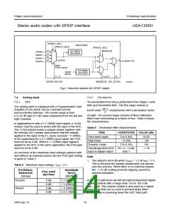
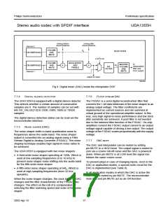
7.8
Digital audio input and output
• LSB-justified; 18 bits
• LSB-justified; 20 bits
• LSB-justified; 24 bits
• MSB-justified.
The selection of the digital audio input and output formats
and master or slave modes differ for static and
microcontroller mode.
In master mode, when 256fs output clock is selected and
the digital interface is master, the BCK output clock will be
64fs. In case 384fs output clock is selected, the BCK output
clock will be 48fs.
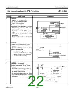
7.9
Power-on reset
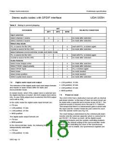
The UDA1355H has a dedicated reset pin with an internal
pull-down resistor. In this way a Power-on reset circuit can
be made with a capacitor and a resistor at pin RESET. The
external resistor is needed since the pad is 5 V tolerant.
This means that there is a transmission gate in series with
the input and the resistor inside the pad cannot be seen
from the outside world (see Fig.10).
In the static mode the digital audio input formats are:
• I2S-bus
• LSB-justified; 16 bits
• LSB-justified; 24 bits
• MSB-justified.
The reset timing is determined by the external pull-down
resistor and the external capacitor which is connected to
pin RESET. At Power-on reset, all the digital sound
processing features and the system controlling features
are set to the default setting of the microcontroller mode.
Since the bit controlling the clock of the synchronous
registers is set to enable, the synchronous registers are
also reset.
The digital audio output formats are:
• I2S-bus
• MSB-justified.
In the microcontroller mode, the following formats are
independently selectable:
• I2S-bus
• LSB-justified; 16 bits
2003 Apr 10
18

 NXP [ NXP ]