Philips Semiconductors
Preliminary specification
Stereo audio codec with SPDIF interface
UDA1355H
8
APPLICATION MODES
In this chapter the application modes for static mode and
microcontroller mode are described.
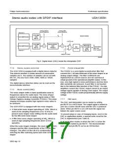
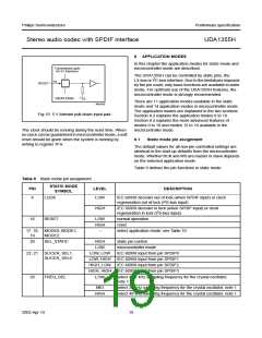
handbook, halfpage
Transmission gate
for 5V tolerance
The UDA1355H can be controlled by static pins, the
L3-bus or I2C-bus interface. Due to the limitations imposed
by the pin count, only basic functions are available in static
mode. For optimum use of the UDA1355H features, the
microcontroller mode is strongly recommended.
16
RESET
V
UDA1355H
SS
There are 11 application modes available in the static
mode and 14 application modes in microcontroller mode.
The application modes are explained in the two sections:
Section 8.2 explains the application modes 0 to 10.
Section 8.4 explains the more advanced features of
modes 0 to 10 and modes 12 to 14 available in the
microcontroller mode.
MGU835
Fig.10 5 V tolerant pull-down input pad.
The clock should be running during the reset time. When
no clock can be guaranteed in microcontroller mode, a soft
reset should be given when the system is running by
writing to register 7FH.
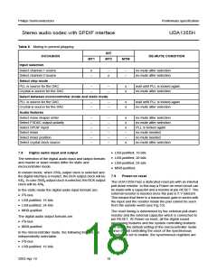
8.1
Static mode pin assignment
The default values for all non-pin controlled settings are
identical to the start-up defaults from the microcontroller
mode. Whether BCK and WS are master or slave depends
on the selected application mode.
Table 9 defines the pin functions in static mode.
Table 9 Static mode pin assignment
STATIC MODE
PIN
LEVEL
DESCRIPTION
SYMBOL
4
LOCK
LOW
IEC 60958 decoder out of lock (when SPDIF input) or clock
regeneration out of lock (I2S-bus input)
HIGH
IEC 60958 decoder in lock (when SPDIF input) or clock
regeneration in lock (I2S-bus input)
16
RESET
LOW
HIGH
−
normal operation
reset
17, 18, MODE0, MODE1,
select application mode; see Table 10
19
MODE2
20
SEL_STATIC
HIGH
LOW
static pin control
microcontroller mode
22, 21 SLICER_SEL1,
SLICER_SEL0
LOW, LOW
LOW, HIGH
IEC 60958 input from pin SPDIF0
IEC 60958 input from pin SPDIF1
HIGH, LOW IEC 60958 input from pin SPDIF2
HIGH, HIGH IEC 60958 input from pin SPDIF3
29
FREQ_SEL
LOW
select 44.1 kHz sampling frequency for the crystal oscillator,
note 1
MID
select 32 kHz sampling frequency for the crystal oscillator, note 1
select 48 kHz sampling frequency for the crystal oscillator, note 1
HIGH
2003 Apr 10
19

 NXP [ NXP ]