Philips Semiconductors
Preliminary specification
Stereo audio codec with SPDIF interface
UDA1355H
7.6.3
DC FILTERING
• Support for 1fs and 2fs input data rate and 192 kHz
audio via I2S-bus.
In the decimator there are two digital DC blocking circuits.
The stereo interpolator has the following sound features:
The first blocking circuit is in front of the volume control to
remove DC bias from the ADC output. The DC bias is
added in the ADC to prevent audio band Idle tones
occurring in the noise shaper. With the DC components
removed, a signal gain of 24 dB can be achieved.
• Linear volume control using 14-bit coefficients with
0.25 dB steps: range 0 to −78 dB and −∞ dB; hold for
master volume and mixing volume control
• A cosine roll-off soft mute with 32 coefficients; each
coefficient is used for four samples, in total 128 samples
are needed to fully mute or de-mute (approximately
3 ms at fs = 44.1 kHz)
The second blocking circuit removes the DC components
introduced by the decimator stage.
• Independent selectable de-emphasis for 32, 44.1, 48
7.6.4
OVERLOAD DETECTION
and 96 kHz for both channels
Bit OVERFLOW = 1 when the output data in the left or
right channel is larger than −1.16 dB of the maximum
possible digital swing. This condition is set for at least
512fs cycles (that is 11.6 ms at fs = 44.1 kHz). This
time-out is reset for each infringement.
• Treble is the selectable positive gain for high
frequencies. The edge frequency of the treble is fixed
and depends on the sampling frequency. Treble can be
set independently for left and right channel with two
settings:
7.7
Analog output
– fc = 1.5 kHz; fs = 44.1 kHz; 0 to 6 dB gain range with
2 dB steps
7.7.1
AUDIO FEATURE PROCESSOR
– fc = 3 kHz; fs = 44.1 kHz; 0 to 6 dB gain range with
2 dB steps.
The audio feature processor provides automatic
de-emphasis for the IEC 60958 bitstream.
In microcontroller mode all features are available and
there is a default mute on start up.
• Normal bass boost is the selectable positive gain for low
frequencies. The edge frequency of the bass boost is
fixed and depends on the sampling frequency. Normal
bass boost can be set independently for the left and right
channel with two sets:
7.7.2
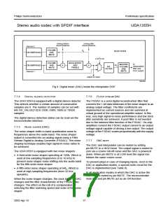
INTERPOLATING FILTER
The digital filter interpolates from 1fs to 64fs, or from
1fs to 128fs, by cascading a half-band filter and a FIR filter.
– fc = 250 Hz; fs = 44.1 kHz; 0 to 18 dB gain range with
2 dB steps
The stereo interpolator has the following basic features:
• 24-bit data path
– fc = 300 Hz; fs = 44.1 kHz; 0 to 24 dB gain range with
2 dB steps.
• Resonant bass boost optional function is selected if
bit BASS_SEL = 1. When selected, the characteristics
are determined by six 14-bit coefficients. Resonant bass
boost controls the left and right channel with the same
characteristics. When resonant bass boost is selected,
the treble control also changes to a single control for
both channels following the gain setting of the left
channel.
• Mixing of two channels:
– To prevent clipping inside the core, there is an
automatic signal level correction of −6 dB scaling
before mixing and +6 dB gain after digital volume
control
– Position of mixing can be set before or after bass
boost and treble
– Master volume control and mute with independent left
and right channel settings for balance control
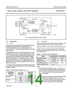
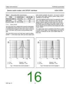
A software program is available for users to generate the
required six 14-bit coefficients by entering the desired
centre frequency (fc), positive or negative peak gain,
sampling frequency (fs) and shape factor (see
Figs 7 and 8).
– Independently left and right channel de-emphasis,
volume control and mute (no left or right)
– Output of the mixer is to the I2S-bus or IEC 60958
decoder.
• Full FIR filter implementation for all the upsampling
filters
• Integrated digital silence detection for left and right
channels with selectable silence detection time
2003 Apr 10
15

 NXP [ NXP ]