Philips Semiconductors
Preliminary specification
Stereo audio codec with SPDIF interface
UDA1355H
Table 7 Interpolation filter characteristics
mute controls available: for source 1, for source 2 and for
the master (sum) signal. All three volume ranges can be
controlled in 0.25 dB steps.
ITEM
CONDITIONS
VALUE (dB)
Pass-band ripple
Stop band
0 to 0.45fs
>0.55fs
±0.035
−60
To prevent clipping inside the mixer, the signals are scaled
with −6 dB before mixing, therefore the sum of the two
signals is always equal to or lower than 0 dB. After the
mixing there is a 6 dB gain in the master volume control.
This means that at the analog output the signal can clip,
but the clipping can be undone by decreasing the master
volume control.
Dynamic range
0 to 0.4535fs
140
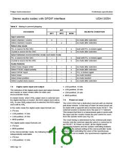
7.7.3
DIGITAL MIXER
The UDA1355H has a digital mixer inside the interpolator.
The digital mixer can be used as a cross over or a selector.
A functional block diagram of the mixer mode is shown in
Fig.9. This mixer can be used in microcontroller mode
only.
The output of the mixer is available via the I2S-bus output
or via the SPDIF output. The output signal of the mixer is
scaled to a maximum of 0 dB, so the digital output can
never clip.
The UDA1355H can be set to the mixer mode by setting
bit MIX = 1. In the mixer mode, there are three volume and
MGU832
MGU831
10
10
handbook, halfpage
handbook, halfpage
gain
(dB)
gain
(dB)
8
8
6
4
6
4
2
2
0
0
−2
−4
−6
−8
−10
−2
−4
−6
−8
−10
2
3
2
3
1
10
10
10
1
10
10
10
f (Hz))
f (Hz))
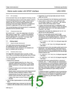
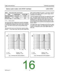
fc = 70 Hz
Peak gain = 10 dB
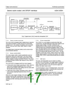
fc = 70 Hz
Peak gain = 10 dB
fs = 44.1 kHz
Shape factor = 1.4142
fs = 44.1 kHz
Shape factor = 1.4142
Fig.7 Resonant bass boost example 1.
Fig.8 Resonant bass boost example 2.
2003 Apr 10
16

 NXP [ NXP ]