Philips Semiconductors
Preliminary specification
Stereo audio codec with SPDIF interface
UDA1355H
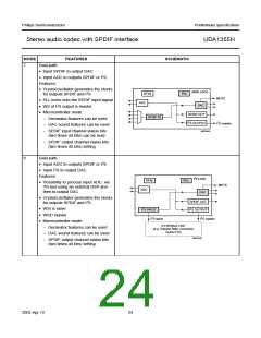
STATIC MODE
PIN
LEVEL
DESCRIPTION
SYMBOL
30, 31 SFOR1, SFOR0
LOW, LOW
LOW, HIGH
set I2S-bus format for digital data input and output interface
set LSB-justified 16 bits format for digital data input interface and
MSB-justified format for digital data output interface
HIGH, LOW set LSB-justified 24 bits format for digital data input interface and
MSB-justified format for digital data output interface
HIGH, HIGH set MSB-justified format for digital data input and output interface
44
MUTE
LOW
normal operation
mute active
HIGH
Note
1. FPLL 256fs is output from pin CLKOUT in PLL locked static mode.
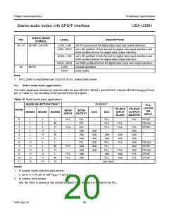
8.2
Static mode basic applications
The static application modes are selected with the pins MODE2, MODE1 and MODE0, with pin MODE0 being a 3-level
pin. In Table 10, the encoding of the pins MODE[2:0] is given.
Table 10 Static mode basic applications
MODE SELECTION PINS(1)
CLOCK(2)
PLL
LOCKS
ON
I2S-BUS I2S-BUS
MODE
SPDIF
INPUT OUTPUT
SPDIF
MODE2 MODE1 MODE0
ADC
DAC
INPUT
SLAVE
OUTPUT
MASTER
INPUT
0
1
L
L
L
L
L
M
H
L
PLL
−
PLL
PLL
PLL
xtal
xtal
xtal
PLL
xtal
xtal
xtal
xtal
−
−
PLL
PLL
PLL
−
−
PLL
−
SPDIF
I2S-bus
SPDIF
−
PLL
PLL
−
2
L
L
PLL
−
−
PLL
xtal
xtal
xtal
xtal
xtal
xtal
PLL
PLL
3
L
H
H
H
L
xtal
xtal
xtal
xtal
xtal
xtal
−
4
L
M
H
L
−
xtal
xtal
xtal
PLL
−
−
5
L
−
xtal
−
6
H
H
H
H
H
H
−
PLL
PLL
PLL
xtal
I2S-bus
SPDIF
I2S-bus
SPDIF
SPDIF
7
L
M
H
L
PLL
−
8
L
PLL
xtal
xtal
9
H
H
H
PLL
PLL
10
11
M
H
−
PLL
not used
Notes
1. In column mode selection pins means:
L: pin at 0 V; M: pin at half VDDD; H: pin at VDDD
.
2. In column clock means:
xtal: the clock is based on the crystal oscillator; PLL: the clock is based on the PLL.
2003 Apr 10
20

 NXP [ NXP ]