Philips Semiconductors
Preliminary specification
Stereo audio codec with SPDIF interface
UDA1355H
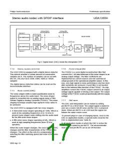
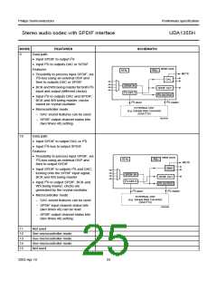
The first 11 application modes are given in this section. Schematic diagrams of these application modes are given in
Table 11. In this table the basic features are mentioned and also the extra features in case of microcontroller mode are
given. It should be noted that the blocks running at the crystal clock (XTAL) are marked unshaded while the blocks
running at the PLL clock are shaded.
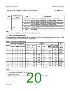
Table 11 Overview of static mode basic applications
MODE
FEATURES
SCHEMATIC
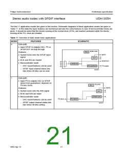
0
Data path:
• Input SPDIF to outputs DAC, I2S or
SPDIFOUT via loop through.
SPDIF LOCK
PLL
Features:
MUTE
• System locks onto the SPDIF input
signal
DAC
• BCK and WS are master
• Microcontroller mode:
SPDIFOUT
SPDIF IN
2
2
I S OUTPUT
I S master
– DAC sound features can be used
– SPDIF input channel status bits
(two times 40 bits) can be read.
MGU836
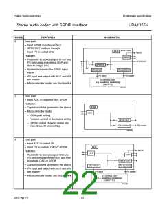
1
Data path:
• Input I2S to outputs DAC or SPDIF
(level II not guaranteed: depends on
I2S-bus clock).
2
I
S LOCK
PLL
MUTE
Features:
• System locks onto the WSI signal
• BCKI and WSI are slave
• Microcontroller mode:
DAC
SPDIF OUT
2
2
I S slave
I S INPUT
– DAC sound features can be used
– SPDIF output channel status bits
(two times 40 bits) setting.
MGU837
2003 Apr 10
21

 NXP [ NXP ]