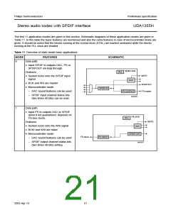
Philips Semiconductors
Preliminary specification
Stereo audio codec with SPDIF interface
UDA1355H
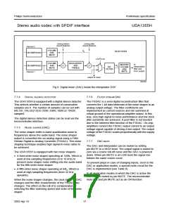
handbook, full pagewidth
mixing before
sound features
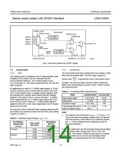
mixing after
sound features
channel 2
VOLUME
AND
1f
UDA1355H
s
DE-EMPHASIS
MUTE
2
L3/I C bit
VOLUME
AND
MUTE
BASS-BOOST
AND
TREBLE
to
MASTER
VOLUME
AND
2f
DE-EMPHASIS
channel 1
s
interpolation
filter and
DAC output
INT.
FILTER
MUTE
output of mixer
MGU834
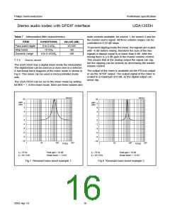
Fig.9 Digital mixer (DAC) inside the interpolator DSP.
7.7.4
DIGITAL SILENCE DETECTOR
7.7.6
FILTER STREAM DAC
The UDA1355H is equipped with a digital silence detector.
This detects whether a certain amount of consecutive
samples are 0. The number of samples can be set with
bits SD_VALUE[1:0] to 3200, 4800, 9600 or 19600
samples.
The FSDAC is a semi digital reconstruction filter that
converts the 1-bit data bitstream of the noise shaper to an
analog output voltage. The filter coefficients are
implemented as current sources and are summed at
virtual ground of the operational amplifier output. In this
way, very high signal-to-noise performance and low clock
jitter sensitivity are achieved. A post filter is not needed
due to the inherent filter function of the FSDAC. On-chip
amplifiers convert the FSDAC output current to an output
voltage signal capable of driving a line output. The output
voltage of the FSDAC scales proportionally with the supply
voltage.
The digital silence detection status can be read via the
microcontroller interface.
7.7.5
NOISE SHAPER (DAC)
The noise shaper shifts in-band quantization noise to
frequencies above the audio band. The noise shaper
output is converted into an analog signal using a Filter
Stream Digital-to-Analog Converter (FSDAC). This noise
shaping technique enables high signal-to-noise ratios to
be achieved.
7.7.7
DAC MUTE
The DAC and interpolator can be muted by setting
pin MUTE to a HIGH level. The output signal is muted to
zero via a cosine roll-off curve and the DAC is powered
down. When pin MUTE is at LOW level the signal rise
follows the same cosine curve.
The UDA1355H is equipped with two noise shapers:
• A third-order noise shaper operating at 128fs. Which is
used at low sampling frequencies (8 to 16 kHz) to
prevent noise shaper noise shifting into the audio band
for the fifth-order noise shaper
To prevent plops in case of changing inputs, clock to the
DAC or application modes, a special mute circuit for the
DAC is implemented (see Table 8).
• A fifth-order noise shaper operating at 64fs. Which is
used at high sampling frequencies (from 32 kHz
upwards).
In all application modes in which the DAC is active the
DAC can be muted by pin MUTE. The microcontroller
mute bits and pin MUTE act as an OR function.
When the noise shaper changes, the clock to the FSDAC
changes and the filter characteristic of the FSDAC also
changes. The effect on the roll of is compensated by
selecting the filter matching speed and order of the noise
shaper.
2003 Apr 10
17

 NXP [ NXP ]