Philips Semiconductors
Preliminary specification
Stereo audio codec with SPDIF interface
UDA1355H
7.4.2
CHANNEL STATUS AND USER BITS
7.5
IEC 60958 encoder
As well as the data bits there are several IEC 60958 key
channel status bits:
When using the crystal oscillator clock, the IEC 60958
encoder output is a full-swing digital signal with level II
timing.
• Pre-emphasis and audio sampling frequency bits
• Two channel PCM indicator bits
• Clock accuracy bits.
When the recovered clock from the PLL is used the
IEC 60958 encoder will function correctly but will not meet
level II timing requirements.
In total 40 status bits per channel are recovered from the
incoming IEC 60958 bitstream. These are readable via the
microcontroller interface.
7.5.1
STATIC MODE
All user and channel status bits are set to logic 0. This is
default value specified by IEC.
User bits, which can contain a large variety of data, such
as CD text, are output to pin SLICER_SEL0 (see Table 4).
In microcontroller mode this signal contains the raw user
bits extracted from the SPDIF bitstream. Signal U_RDY
gives a pulse on pin MODE2 each time there is a new user
bit available. Both signals can be used by an external
microcontroller to grab and decode the user bits.
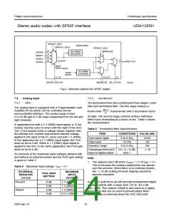
In static mode 0 and 2, the selected SPDIF input channel
can be looped through to pin SPDIFOUT (see Fig.6).
7.5.2
MICROCONTROLLER MODE
Two times 40 channel status bits can be set. Default value
for each status bit is logic 0. When setting the channel
status bits, it is possible to set only the left channel status
bits and have the bits copied to the right channel.
Table 4 Signal names in microcontroller mode
PIN NAME
SLICER_SEL0
SIGNAL NAME
USER
The procedure of writing the channel status bits is as
follows:
MODE2
U_RDY
1. Set bit SPDO_VALID = 0 to prevent immediately
sending the status bits during writing.
SLICER_SEL1
AC3
2. Set bit l_r_copy = 1 if the right channel needs the
same status bits as the left channel or set
bit l_r_copy = 0 if the right channel needs different
status bits to the left channel.
7.4.3
DIGITAL DATA
Audio and digital data can be transmitted in the SPDIF
bitstream. The PCM channel status bit should be set to
logic 1 if the SPDIF bitstream is carrying digital data
instead of audio data, but in practice it proves that not all
equipment handles these channel status bits properly.
3. Write the left and right channel status bits.
4. Set bit SPDO_VALID = 1 after writing all channel
status bits to the register. Starting from the next SPDIF
block the IEC 60958 encoder will use the new status
bits.
In the UDA1355H, digital data is detected via bit PCM, or
via the sync bytes as specified by IEC. These sync bytes
are two sync words, F872H and 4E1FH (two subframes)
preceded by four or more subframes filled with zeros.
Signal AC3 is kept HIGH for 4096 frames when the
UDA1355H detects this burst preamble. Signal AC3 is
present on pin SLICER_SEL1 in microcontroller mode
(see Table 4).
In microcontroller modes 2 and 13, the selected SPDIF
input channel can be looped through to pin SPDIFOUT
(see Fig.6).
2003 Apr 10
13

 NXP [ NXP ]