Philips Semiconductors
Preliminary specification
Stereo audio codec with SPDIF interface
UDA1355H
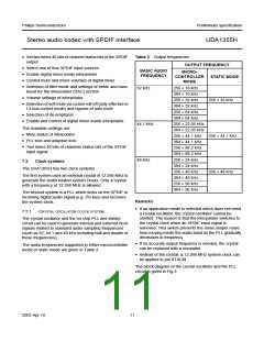
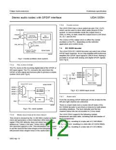
7.3.4
CLOCK OUTPUT
The UDA1355H has a clock output pin (pin CLK_OUT),
which can be used to drive other audio devices in the
system. In microcontroller mode the output clock is
256fs or 384fs. In static mode the output clock is 256 times
32, 44.1 and 48 kHz.
12.288 MHz
handbook, halfpage
13
14
XTALIN
CRYSTAL
OSCILLATOR
PLL
MODULE
XTALOUT
The source of the output clock is either the crystal
oscillator or the PLL, depending on the selected
application and control mode.
256f or 384f clock
s
s
11
CLK_OUT
PLL clock
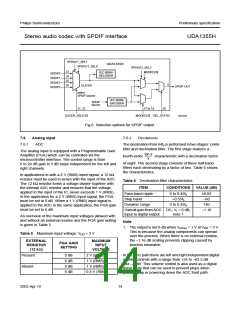
7.4
IEC 60958 decoder
2
L3-bus or I C-bus
register setting
UDA1355H
The UDA1355H IEC 60958 decoder can select one of four
SPDIF input channels. An on-chip amplifier with hysteresis
amplifies the SPDIF input signal to CMOS level, making it
possible to accept both analog and digital SPDIF signals
(see Fig.5).
MGU830
Fig.3 Crystal oscillator clock system.
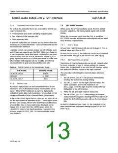
PLL CLOCK SYSTEM
7.3.2
The PLL locks on the incoming digital data of the SPDIF or
WS input signal. The PLL recovers the clock from the
SPDIF or WSI signal and removes jitter to produce a stable
system clock (see Fig.4).
handbook, halfpage
23
24
SPDIF0
SPDIF1
10 nF
25
26
SPDIF2
SPDIF3
75 Ω
180 pF
UDA1355H
select SPDIF source
UDA1355H
MGU829
23
SPDIF0
24
SPDIF1
IEC 60958
DECODER
Fig.5 IEC 60958 input circuit.
25
SPDIF2
SPDIF3
26
2
7.4.1
AUDIO DATA
SLICER
256f
or
384f
s
s
PLL
From the incoming SPDIF bitstream 24 bits of data for the
left and right channel are extracted.
WSI
MGU827
There is a hard mute (not a cosine roll-off mute) if the
IEC 60958 decoder is out of lock or detects bi-mark phase
encoding violations. The lock indicator and the key
channel status bits are accessible in L3-bus mode.
Fig.4 PLL clock system.
The UDA1355H supports the following sample
frequencies and data rates, including half and double of
these frequencies:
7.3.3
WORD SELECTION DETECTION CIRCUIT
This circuit is clocked by the 12.288 MHz crystal oscillator
clock and generates a Word Selection (WS) detection
signal. If the WS detector does not detect any WS edge,
defined as 7 times LOW and 7 times HIGH, then the
WS detection signal is LOW. This information can be used
to set the clock for the noise shaper in the interpolator. This
will prevent noise shaper noise in the audio band.
• fs = 32 kHz; resulting in a data rate of 2.048 Mbit/s
• fs = 44.1 kHz; resulting in a data rate of 2.8224 Mbit/s
• fs = 48 kHz; resulting in a data rate of 3.072 Mbit/s.
2003 Apr 10
12

 NXP [ NXP ]