Philips Semiconductors
Preliminary specification
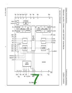
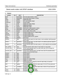
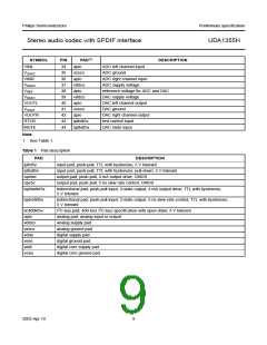
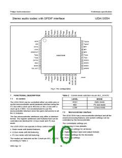
Stereo audio codec with SPDIF interface
UDA1355H
• Set two times 40 bits of channel status bits of the SPDIF
output
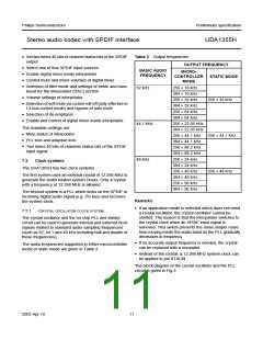
Table 3 Output frequencies
OUTPUT FREQUENCY
• Select one of four SPDIF input sources
• Enable digital mixer inside interpolator
• Control mute and mixer volumes of digital mixer
BASIC AUDIO
FREQUENCY
MICRO-
CONTROLLER
MODE
STATIC MODE
• Selection of filter mode and settings of treble and bass
boost for the interpolator (DAC) section
32 kHz
44.1 kHz
48 kHz
256 × 16 kHz
384 × 16 kHz
256 × 32 kHz
384 × 32 kHz
256 × 64 kHz
384 × 64 kHz
256 × 22.05 kHz
384 × 22.05 kHz
256 × 44.1 kHz
384 × 44.1 kHz
256 × 88.2 kHz
384 × 88.2 kHz
256 × 24 kHz
384 × 24 kHz
256 × 48 kHz
384 × 48 kHz
256 × 96 kHz
384 × 96 kHz
• Volume settings of interpolator
256 × 32 kHz
• Selection of soft mute via cosine roll-off (only effective in
L3-bus control mode) and bypass of auto mute
• Selection of de-emphasis
• Enable and control of digital mixer inside interpolator.
The readable settings are:
• Mute status of interpolator
• PLL lock and adaptive lock
256 × 44.1 kHz
• Two times 40 bits of channels status bits of the SPDIF
input signal.
7.3
Clock systems
The UDA1355H has two clock systems.
256 × 48 kHz
The first system uses an external crystal of 12.288 MHz to
generate the audio related system clocks. Only a crystal
with a frequency of 12.288 MHz is allowed.
The second system is a PLL which locks on the SPDIF or
incoming digital audio signal (e.g. I2S-bus) and recovers
the system clock.
Remarks:
• If an application mode is selected which does not need
a crystal oscillator, the crystal oscillator cannot be
omitted. The reason is that the interpolator switches to
the crystal clock when an SPDIF input signal is
removed. This switch prevents the noise shaper noise
from moving inside the audio band as the PLL gradually
decreases in frequency.
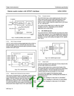
7.3.1
CRYSTAL OSCILLATOR CLOCK SYSTEM
The crystal oscillator and the on-chip PLL and divider
circuit can be used to generate internal and external clock
signals related to standard audio sampling frequencies
(such as 32, 44.1 and 48 kHz including half and double of
these frequencies).
• If no accurate output frequency is needed, the crystal
can be replaced with a resonator.
The audio frequencies supported in either microcontroller
mode or static mode are given in Table 3.
• Instead of the crystal, a 12.288 MHz system clock can
be applied to pin XTALIN.
The block diagram of the crystal oscillator and the PLL
circuit is given in Fig.3.
2003 Apr 10
11

 NXP [ NXP ]