Philips Semiconductors
Preliminary specification
Stereo audio codec with SPDIF interface
UDA1355H
handbook, full pagewidth
V
V
1
2
3
4
5
6
7
8
9
33
32
BCKI
WSI
ADCN
ADCP
DATAI
31 MP2
30 MP1
LOCK
SPDIFOUT
29 MP0
V
V
28
27
DDE
SSIS
DDI
UDA1355H
V
V
SSE
26 SPDIF3
25 SPDIF2
24 SPDIF1
23 SPDIF0
DATAO
WSO
BCKO 10
CLK_OUT 11
MGU828
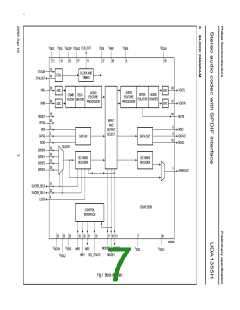
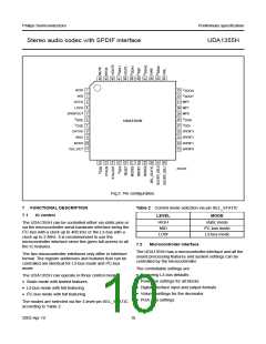
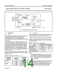
Fig.2 Pin configuration.
7
FUNCTIONAL DESCRIPTION
IC control
Table 2 Control mode selection via pin SEL_STATIC
7.1
LEVEL
MODE
HIGH
MID
static mode
I2C-bus mode
L3-bus mode
The UDA1355H can be controlled either via static pins or
via the microcontroller serial hardware interface being the
I2C-bus with a clock up to 400 kHz or the L3-bus with a
clock up to 2 MHz. It is recommended to use the
microcontroller interface since this gives full access to all
the IC features.
LOW
7.2
Microcontroller interface
The UDA1355H has a microcontroller interface and all the
sound processing features and system settings can be
controlled by the microcontroller.
The two microcontroller interfaces only differ in interface
format. The register addresses and features that can be
controlled are identical for L3-bus mode and I2C-bus
mode.
The controllable settings are:
• Restoring L3-bus defaults
The UDA1355H can operate in three control modes:
• Static mode with limited features
• Power-on settings for all blocks
• Digital interface input and output formats
• Volume settings for the decimator
• PGA gain settings
• L3-bus mode with full featuring
• I2C-bus mode with full featuring.
The modes are selected via the 3-level pin SEL_STATIC
according to Table 2.
2003 Apr 10
10

 NXP [ NXP ]