Philips Semiconductors
Product specification
Multimedia bridge, high performance
Scaler and PCI circuit (SPCI)
SAA7146A
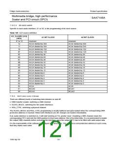
7.16.5.4 Bit clock control
Specific to each audio interface, A1 or A2, is the programming of bit clock source.
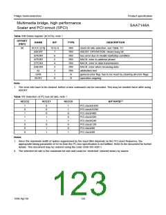
Table 109 CLK source definition
AX_CLKSRC [4:0]
A1 BIT CLOCK
(HEX)
A2 BIT CLOCK
1F to 13
12
reserved
reserved
ACLK divided-by-384
ACLK divided-by-256
ACLK divided-by-192
ACLK divided-by-128
ACLK divided-by-96
ACLK divided-by-64
ACLK divided-by-48
ACLK divided-by-32
ACLK divided-by-24
ACLK divided-by-16
ACLK divided-by-12
ACLK divided-by-8
ACLK divided-by-6
ACLK divided-by-4
ACLK divided-by-3
ACLK divided-by-2
ACLK
11
10
0F
0E
0D
0C
0B
0A
09
08
07
06
05
04
03
02
01
BCLK2
BCLK1
00
BCLK1
BCLK2
7.16.6 SWITCHING AUDIO STREAMS
There are different levels of switching data streams on and off:
• DMA transfer enable; switching a DMA channel
• AUDIO_MODE; switching the two audio interfaces
• WSx_CTRL; switching a physical channel.
The AUDIO_MODE and WSx_CTRL programming is locally buffered and gets loaded when the corresponding DMA
protection address is reached. When both interfaces are off, changes are loaded immediately.
If an audio interface is switched on, it will start working at TSL pointer reset. Disabling a DMA channel clears the
corresponding FIFO and sets the DMA pointers to their base address: this is the initial state. It is recommended to enable
the output DMA channels before activating the interface, since the output FIFO has to be filled with valid output data.
It is the responsibility of the software to configure data structures, TSL sequences and protection address in such a way,
that they match each other.
1998 Apr 09
121

 NXP [ NXP ]