Philips Semiconductors
Product specification
Multimedia bridge, high performance
Scaler and PCI circuit (SPCI)
SAA7146A
7.16.5.2 Audio input level monitoring
The audio input level monitoring feature allows the control of audio input levels without additional external hardware, by
comparing the absolute value of the most significant byte of an audio sample to a programmable reference maximum
level. The MAXLEVEL is defined by 7 bits, since serial audio data is transmitted in twos complement and the sign of the
compared byte is not relevant for audio level control. Therefore, MAXLEVEL is programmable from 0 to 127. The twos
complement value −128 is not reachable, but also not functionally needed. The comparison results are stored in the
32-bit level report register with one bit per time slot of TSL1 and TSL2, reporting whether there was a level violation in
that time slot. The comparison runs all the time and the level report register is reset when it is read by software.
Table 106 Level report register
OFFSET
(HEX)
NAME
BIT
TYPE
DESCRIPTION
140
LEVEL_REPORT
31 to 0
R
stores the violation of MAXLEVEL for all 32 TSL records;
reset to 0000H when read.
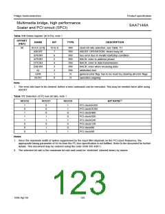
7.16.5.3 WS line controlling
The WSx_CTRL bits define which of the WS lines is output and controlled by which audio interface circuit (A1 or A2).
WSx_SYNC defines the timing of WS signals.
Table 107 Static function control for word select lines
WSx_CTRL
WS0 FUNCTION WS1 FUNCTION
WS2 FUNCTION
WS3 FUNCTION
WS4 FUNCTION
[1:0]
00
3-state, input,
rising edge resets
TSL1 pointer
3-state
3-state
3-state
3-state, input,
rising edge resets
TSL2 pointer
01
10
11
output, controlled output, controlled output, controlled
by TSL1 by TSL1 by TSL1
output, controlled output, controlled output, controlled
output, controlled
by TSL1
output, controlled
by TSL1
output, controlled
by TSL2
output, controlled
by TSL2
by TSL2
by TSL2
by TSL2
output,
output,
output, active LOW output, active LOW output, active LOW
active LOW
active LOW
Table 108 Pulse width and position control
WSx_SYNC
[1:0]
PULSE FUNCTION
00
01
10
11
I2S style: WS goes active one bit clock cycle before MSB of time slot and stays active until LSB, i.e. one
bit clock before MSB of next time slot
WS goes active in sync with MSB and stays active until next MSB, i.e. active in sync with current time
slot
WS goes active one bit clock before MSB and stays active for one bit clock cycle, i.e. negative edge is
in sync with beginning of time slot
SINGER style: WS goes active in sync with MSB and stays active for one bit clock cycle and for two bit
clock cycles in first time slot of the superframe
1998 Apr 09
120

 NXP [ NXP ]